technical data Synchronous Belts and Belt Sprockets design data
Layout Design
Guide flange installation
Synchronous Belts tend to shift to one side in the axial direction of the pulley during operation. Therefore, a guide flange is attached to the pulley to prevent Synchronous Belts from coming off the pulley. The installation standards for guide flanges are as follows:
Horizontal shaft transmission
Attach guide flanges to both sides of one pulley, or to the opposite sides of both pulleys (Example 1).
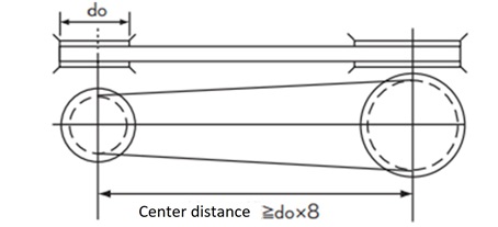
Also, if the distance between the pulley axes is eight times or more the outer diameter of the small pulley, attach guide flanges to both sides of both pulleys. (Example 2)
(Example 1)
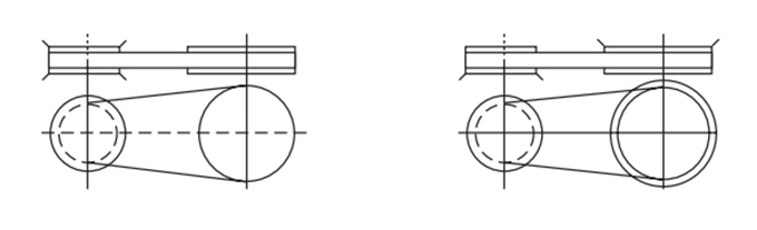
(Example 2)
Vertical shaft transmission
Since the belt may come off downwards due to its own weight, attach guide flanges to both sides of one pulley and the underside of the other pulley.
multi-axis shaft transmission
Attach guide flanges to both sides of every other pulley (Example 3) or to one side of every pulley (Example 4).

Use of idlers
Idler is used in the following cases:
- - When the bearing is fixed and installation tension is to be adjusted
- ・When the speed ratio is large and the number of meshing teeth of the small pulley is increased
- ・When the belt cannot be guided by the drive and driven pulleys
Precautions when using idlers
- - The idler should be fixed and, in principle, used on the slack side.
- - If the idler and both sides are not parallel to each other, the idler may cause the belt to come off the pulley, so please be careful.
- ・Decide the idler diameter as follows:
- Inner idler... Belt Sprockets with at least the minimum number of teeth shown in the table below.
- Outer idler: A flat pulley with no crown, with a diameter at least 1.2 times the pitch circle diameter of the pulley in the table below.
Minimum number of pulley teeth when selecting an idler
| kinds | Rotational speed r/min | |||
|---|---|---|---|---|
| Under 900 | Over 900 Under 1200 |
Over 1200 Under 1800 |
Over 1800 3600 or less |
|
| P2M | 16 | 16 | 18 | 20 |
| P3M・UP3M | 14 | 14 | 16 | 18 |
| P5M・UP5M | 18 | 20 | 24 | 28 |
| P8M・UP8M | 24 | 26 | 26 | 28 |
| P14M・UP14M | 28 | 28 | 28 | 34 |
Note: For speeds exceeding 3600 r/min, refer to the standard transmission capacity table.

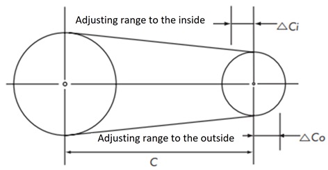
Adjustment of distance between two axes
When transmitting power using only drive and driven pulleys without using idlers, provide an adjustment allowance for the center distance in the bearings, including the manufactured length (tolerance) of the belt.
Adjusting margin of inter-axial distance
| Belt length | kinds | ||
|---|---|---|---|
| P2M・P3M・P5M UP3M・UP5M |
P8M・P14M UP8M・UP14M |
||
| △Co | Under 500 | 3 | 3 |
| 500~1000 | 5 | 5 | |
| 1001~2000 | 10 | 10 | |
| Over 2000 | 15 | 15 | |
| △Ci | common | 10 | 15 |
Installation tension and shaft load
Belt installation tension
Synchronous Belts are meshing transmissions, but proper installation tension is required to prevent tooth jumping and ensure smooth transmission. If installation tension is too weak, it may cause misalignment of the meshing, and if it is too strong, it may generate noise, both of which shorten the life of the belt. Please refer to the sonic belt tension meter available, which can accurately measure tension.
How to apply installation tension
- 1. Accurately check the parallelism of all shafts, including the idler shaft, and the alignment of the pulleys.
- 2. Apply a pressure force (F) to the center of the belt span.
- 3. Apply tension so that the belt deflection (δ) is 1.6 mm per 100 mm of span.
How to calculate Pressing force (F)
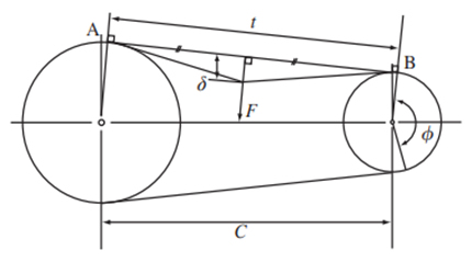
F = Ti + t × Y L 16
- F: Deflection (δ) at the center of span t
Required Pressing force N{kgf} - Ti: installation tension N{kgf}
- Y: Correction coefficient
- δ: Deflection mm=0.016t
- t: span length mm
t = C2 - (Dp - dp)2 4
- C: Center distance mm
- Dp: Pitch circle diameter of large pulley mm
- dp: Small pulley pitch circle diameter mm
- L: Belt length mm
Axial load
The axial load can be calculated using the following formula:
Axial load = 2 Ti × sin Φ 2
- Ti: installation tension N{kgf}
- Φ: Pulley winding angle (degrees)
installation tension list
Ultra PX Belt HC type
| Types (pitch) |
Belt width mm |
installation tension Ti N {kgf} | Correction coefficient YN {kgf} | |
|---|---|---|---|---|
| Recommended value | Maximum | |||
| UP3M-HC | 6 | 29 {3.0} | 40 {4.1} | 38.5 {3.9} |
| 10 | 52 {5.3} | 72 {7.3} | 61.8 {6.3} | |
| 15 | 82 {8.4} | 114 {11.6} | 90 {9.2} | |
| UP5M-HC | 10 | 108 {11.0} | 147 {15.0} | 102.7 {10.5} |
| 15 | 171 {17.4} | 232 {23.7} | 152 {15.5} | |
| 20 | 238 {24.3} | 323 {32.9} | 200.7 {20.5} | |
| 25 | 307 {31.3} | 418 {42.6} | 249.1 {25.4} | |
| 30 | 377 {38.4} | 513 {52.3} | 297.2 {30.3} | |
| 35 | 450 {45.9} | 613 {62.5} | 344.9 {35.2} | |
| 40 | 524 {53.4} | 713 {72.7} | 392.5 {40.0} | |
| UP8M-HC | 15 | 177 {18.0} | 235 {24.0} | 190.6 {19.4} |
| 20 | 244 {24.9} | 324 {33.0} | 246 {25.1} | |
| 25 | 317 {32.3} | 421 {42.9} | 299.9 {30.6} | |
| 30 | 389 {39.7} | 517 {52.7} | 352.6 {36.0} | |
| 35 | 464 {47.3} | 616 {62.8} | 404.3 {41.2} | |
| 40 | 540 {55.1} | 717 {73.1} | 455.1 {46.4} | |
| 45 | 618 {63.0} | 820 {83.6} | 505.2 {51.5} | |
| 50 | 697 {71.1} | 926 {94.4} | 554.7 {56.6} | |
| 55 | 777 {79.2} | 1032 {105.2} | 603.7 {61.6} | |
| 60 | 859 {87.6} | 1140 {116.2} | 652.2 {66.5} | |
| UP14M-HC | 40 | 794 {81.0} | 1050 {107.1} | 834 {85.0} |
| 60 | 1255 {128.0} | 1659 {169.2} | 1242.7 {126.7} | |
| 80 | 1747 {178.1} | 2310 {235.6} | 1649.0 {168.2} | |
| 100 | 2255 {229.9} | 2982 {304.1} | 2053.6 {209.4} | |
| 120 | 2771 {282.6} | 3665 {373.7} | 2456.9 {250.5} | |
Ultra PX Belt HA specification
| Types (pitch) |
Belt width mm |
installation tension Ti N {kgf} | Correction coefficient YN {kgf} | |
|---|---|---|---|---|
| Recommended value | Maximum | |||
| UP5M-HA | 10 | 108 {11.0} | 147 {15.0} | 102.7 {10.5} |
| 15 | 171 {17.4} | 232 {23.7} | 152.0 {15.5} | |
| 20 | 238 {24.3} | 323 {32.9} | 200.7 {20.5} | |
| 25 | 307 {31.3} | 418 {42.6} | 249.1 {25.4} | |
| 30 | 377 {38.4} | 513 {52.3} | 297.2 {30.3} | |
| 35 | 450 {45.9} | 613 {62.5} | 344.9 {35.2} | |
| 40 | 524 {53.4} | 713 {72.7} | 392.5 {40.0} | |
| UP8M-HA | 15 | 177 {18.0} | 235 {24.0} | 190.6 {19.4} |
| 20 | 244 {24.9} | 324 {33.0} | 246.0 {25.1} | |
| 25 | 317 {32.3} | 421 {42.9} | 299.9 {30.6} | |
| 30 | 389 {39.7} | 517 {52.7} | 352.6 {36.0} | |
| 35 | 464 {47.3} | 616 {62.8} | 404.3 {41.2} | |
| 40 | 540 {55.1} | 717 {73.1} | 455.1 {46.4} | |
| 45 | 618 {63.0} | 820 {83.6} | 505.2 {51.5} | |
| 50 | 697 {71.1} | 926 {94.4} | 554.7 {56.6} | |
| 55 | 777 {79.2} | 1032 {105.2} | 603.7 {61.6} | |
| 60 | 859 {87.6} | 1140 {116.2} | 652.2 {66.5} | |
| UP14M-HA | 40 | 794 {81.0} | 1050 {107.1} | 834.0 {85.0} |
| 60 | 1255 {128.0} | 1659 {169.2} | 1242.7 {126.7} | |
| 80 | 1747 {178.1} | 2310 {235.6} | 1649.0 {168.2} | |
| 100 | 2255 {229.9} | 2982 {304.1} | 2053.6 {209.4} | |
| 120 | 2771 {282.6} | 3665 {373.7} | 2456.9 {250.5} | |
Ultra PX belt HY type
| Types (pitch) |
Belt width mm |
installation tension Ti N {kgf} | Correction coefficient YN {kgf} | |
|---|---|---|---|---|
| Recommended value | Maximum | |||
| UP3M-HY | 6 | 39 {4.0} | 47 {4.8} | 76.0 {7.7 } |
| 10 | 68 {6.9} | 82 {8.4} | 118.2 {12.1} | |
| 15 | 105 {10.7} | 127 {13.0} | 167.7 {17.1} | |
| UP5M-HY | 10 | 125 {12.7} | 165 {16.8} | 152.5 {15.6} |
| 15 | 194 {19.8} | 256 {26.1} | 223.7 {22.8 } | |
| 20 | 265 {27.0} | 350 {35.7} | 293.6 {29.9} | |
| 25 | 338 {34.5} | 446 {45.5} | 362.6 {37.0 } | |
| 30 | 413 {42.1} | 545 {55.6} | 430.8 {43.9 } | |
| 35 | 488 {49.8} | 644 {65.7} | 498.4 {50.8 } | |
| 40 | 564 {57.5} | 744 {75.9} | 565.4 {57.7 } | |
| UP8M-HY | 15 | 255 {26.0} | 290 {29.6} | 272.0 {27.7 } |
| 20 | 347 {35.4} | 394 {40.2} | 341.3 {34.8 } | |
| 25 | 444 {45.3} | 505 {51.5} | 406.9 {41.5 } | |
| 30 | 541 {55.2} | 615 {62.7} | 469.9 {47.9} | |
| 35 | 640 {65.3} | 728 {74.2} | 530.6 {54.1 } | |
| 40 | 740 {75.5} | 841 {85.8} | 589.6 {60.1 } | |
| 45 | 842 {85.9} | 957 {97.6} | 647.0 {66.0 } | |
| 50 | 944 {96.3} | 1073 {109.4} | 703.0 {71.7} | |
| 55 | 1048 {106.9} | 1192 {121.6} | 757.9 {77.3} | |
| 60 | 1150 {117.3} | 1308 {133.4} | 811.8 {82.8} | |
| UP14M-HY | 40 | 1020 {104.0} | 1225 {124.9} | 1044.3 {106.5} |
| 60 | 1581 {161.2} | 1899 {193.6} | 1537.5 {156.8} | |
| 80 | 2162 {220.5} | 2597 {264.8} | 2023.1 {206.3} | |
| 100 | 2754 {280.8} | 3308 {337.3} | 2053.1 {209.4} | |
| 120 | 3366 {343.2} | 4043 {412.3} | 2978.6 {303.7} | |
PX Belt SHINAYAKA 530 (for endless belts)
| Types (pitch) |
Belt width mm |
installation tension Ti N {kgf} | Correction coefficient YN {kgf} | |
|---|---|---|---|---|
| Recommended value | Maximum | |||
| P2M-530 | 4 | 5.9 {0.6} | 7.8 {0.8} | 10.0 {1.0 } |
| 6 | 9.4 {1.0} | 12 {1.2} | 16.1 {1.6} | |
| 10 | 17 {1.7} | 22 {2.2} | 28.2 {2.9} | |
| P3M-530 | 6 | 20 {2.0} | 26 {2.7} | 17.6 {1.8} |
| 10 | 36 {3.7} | 47 {4.8} | 29.0 {3.0 } | |
| 15 | 57 {5.8} | 74 {7.5} | 43.1 {4.4 } | |
PX Belt (for Open-ended belt)
| Types (pitch) |
Belt width mm |
installation tension Ti N {kgf} | Correction coefficient YN {kgf} | |
|---|---|---|---|---|
| Recommended value | Maximum | |||
| P2M | 4 | 5.9 {0.6} | 7.8 {0.8} | 10.0 {1.0 } |
| 6 | 9.4 {1.0} | 12 {1.2} | 16.1 {1.6 } | |
| 10 | 17 {1.7} | 22 {2.2} | 28.2 {2.9} | |
| P3M | 6 | 20 {2.0} | 26 {2.7} | 17.6 {1.8 } |
| 10 | 36 {3.7} | 47 {4.8} | 29.0 {3.0} | |
| 15 | 57 {5.8} | 74 {7.5} | 43.1 {4.4} | |
PX belt RC type
| Types (pitch) |
Belt width mm |
installation tension Ti N {kgf} | Correction coefficient YN {kgf} | |
|---|---|---|---|---|
| Recommended value | Maximum | |||
| P2M-RC | 4 | 5.9 {0.6} | 7.8 {0.8} | 10.0 {1.0} |
| 6 | 9.4 {1.0} | 12 {1.2} | 16.1 {1.6} | |
| 10 | 17 {1.7} | 22 {2.2} | 28.2 {2.9} | |
| P3M-RC | 6 | 20 {2.0} | 26 {2.7} | 17.6 {1.8} |
| 10 | 36 {3.7} | 47 {4.8} | 29.0 {3.0} | |
| 15 | 57 {5.8} | 74 {7.5} | 43.1 {4.4} | |
| P5M-RC | 10 | 97 {9.9} | 132 {13.5} | 56.9 {5.8} |
| 15 | 154 {15.7} | 209 {21.3} | 82.4 {8.4} | |
| 20 | 214 {21.8} | 291 {29.6} | 139.0 {14.2} | |
| 25 | 276 {28.2} | 376 {38.4} | 201.0 {20.5} | |
| P8M-RC | 15 | 203 {20.6} | 265 {27.0} | 151.3 {15.4} |
| 20 | 280 {28.5} | 365 {37.3} | 193.0 {19.7} | |
| 25 | 363 {37.0} | 473 {48.3} | 233.0 {23.8} | |
| 40 | 617 {63.0} | 807 {82.3} | 346.6 {35.3} | |
| 60 | 982 {100.1} | 1283 {130.9} | 488.3 {49.8} | |
| P14M-RC | 40 | 990 {101.0} | 1310 {133.6} | 635.5 {64.8} |
| 60 | 1564 {159.5} | 2070 {211.1} | 973.2 {99.2} | |
| 80 | 2178 {222.1} | 2882 {293.9} | 1316.8 {134.3} | |
| 100 | 2812 {286.7} | 3720 {379.3} | 1664.9 {169.8} | |
| 120 | 3455 {352.3} | 4572 {466.2} | 2016.6 {205.6} | |
PX Belt
| Types (pitch) |
Belt width mm |
installation tension Ti N {kgf} | Correction coefficient YN {kgf} | |
|---|---|---|---|---|
| Recommended value | Maximum | |||
| P5M | 10 | 108 {11.0} | 147 {15.0} | 56.9 {5.8} |
| 15 | 171 {17.4} | 232 {23.7} | 82.4 {8.4} | |
| 20 | 238 {24.3} | 323 {32.9} | 139.0 {14.2} | |
| 25 | 307 {31.3} | 418 {42.6} | 201.0 {20.5} | |
| P8M | 15 | 225 {22.9} | 294 {30.0} | 151.3 {15.4} |
| 20 | 311 {31.7} | 406 {41.4} | 193.0 {19.7} | |
| 25 | 403 {41.1} | 526 {53.6} | 233.0 {23.8} | |
| 40 | 686 {70.0} | 897 {91.5} | 346.6 {35.3} | |
| 60 | 1091 {111.3} | 1426 {145.4} | 488.3 {49.8} | |
| P14M | 40 | 990 {101.0} | 1310 {133.6} | 635.5 {64.8} |
| 60 | 1564 {159.5} | 2070 {211.1} | 973.2 {99.2} | |
| 80 | 2178 {222.1} | 2882 {293.9} | 1316.8 {134.3} | |
| 100 | 2812 {286.7} | 3720 {379.3} | 1664.9 {169.8} | |
| 120 | 3455 {352.3} | 4572 {466.2} | 2016.6 {205.6} | |
PX Belt (Water Resistant)
| Types (pitch) |
Belt width mm |
installation tension Ti N {kgf} | Correction coefficient YN {kgf} | |
|---|---|---|---|---|
| Recommended value | Maximum | |||
| P5M-W | 10 | 108 {11.0} | 147 {15.0} | 50.1 {5.1} |
| 15 | 171 {17.4} | 232 {23.7} | 74.2 {7.6} | |
| 25 | 307 {31.3} | 418 {42.6} | 184.9 {18.9} | |
| P8M-W | 15 | 225 {22.9} | 294 {30.0} | 147.2 {15.0} |
| 25 | 403 {41.1} | 526 {53.6} | 226.7 {23.1} | |
| 40 | 686 {70.0} | 897 {91.5} | 337.3 {34.4} | |
| 60 | 1091 {111.3} | 1426 {145.4} | 475.2 {48.5} | |
Pulley alignment
Even if the pulley alignment is correct, Synchronous Belts will not rotate in the center of the pulley, but will tend to lean to one side. Although this force is very weak, if the pulley alignment is poor, the belt will be pressed hard against the pulley flange, causing it to break or snap. Therefore, adjust the pulley alignment within the tolerances in the table below.
Pulley alignment tolerance
| Belt size | All varieties | |||
|---|---|---|---|---|
| Belt width mm | 30 or less | 30~50 | 50~100 | Over 100 |
| Allowable parallelism | Under 51000 | Under 41000 | Under31000 | Under 21000 |
| θ minutes | 17 or less | 13 or less | 10 or less | 6 or less |

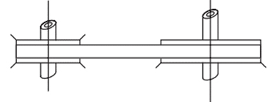
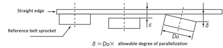
How to adjust the pulley
As shown in the figure, a straight edge is placed on the reference pulley, and the other pulleys are brought into contact with the straight edge on their entire surfaces (ε=0), allowing the pulleys to be lined up in the correct positions.
In addition, by keeping δ in the figure below the limit, it is possible to achieve parallelism of the axis at the same time.
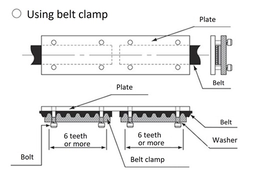
Open-ended belt
Connection Method
Belt dimensional tolerance
Belt length tolerance
| PX Belt Ultra PX Belt |
Tolerance |
|---|---|
| 256 or less | ±0.41 |
| Over 256 and under 3384 | ±0.46 |
| Over 384 and under 3512 | ±0.51 |
| Over 512 and under 3760 | ±0.61 |
| Over 760 and under 1016 | ±0.66 |
| Over 1016 and under 1272 | ±0.76 |
| Over 1272 and under 1528 | ±0.81 |
| Over 1528 and under 1776 | ±0.86 |
| Over 1776 and under 2032 | ±0.91 |
| Over 2032 and under 2288 | ±0.97 |
| Over 2288 and under 2544 | ±1.02 |
| Over 2544 and under 2792 | ±1.07 |
| Over 2792 and under 3048 | ±1.12 |
| Over 3048 and under 3304 | ±1.17 |
| Over 3304 and under 3560 | ±1.22 |
| Over 3560 and under 3808 | ±1.26 |
| Over 3808 and under 4064 | ±1.32 |
| Over 4064 and under 4320 | ±1.37 |
| Over 4320 and under 4576 | ±1.42 |
Belt width tolerance
| Belt width | Belt length | ||
|---|---|---|---|
| 840 or less | Over 840 1680 or less |
1680 Something that exceeds |
|
| 10 or less | +0.3 -0.6 |
+0.6 -0.6 |
- |
| Over 10 and under 45 | +0.8 -0.8 |
+0.8 -1.2 |
+0.8 -1.2 |
| Over 45 and under 75 | +1.2 -1.6 |
+1.6 -1.6 |
+1.6 -1.6 |
| Over 75 and under 100 | +1.6 -1.6 |
+1.6 -2.0 |
+2.0 -2.0 |
| Over 100 | +2.4 -2.4 |
+2.4 -2.8 |
+2.4 -3.2 |
Pulley material and unit mass
The following pulley materials are suitable:
Pulley material and unit mass
| Material | Material Symbol | unit mass |
|---|---|---|
| Carbon steel for machine structures | S45C | 7.85 |
| aluminum alloy | A2017-T4 | 2.8 |
| stainless steel | SUS304 | 7.8 |
General formula for pulley design
・Pitch circle diameter Dp = N × p π
・Tooth tip diameter Do = Dp- 2 a = N × p π -2 a
- p: Belt pitch mm
- N: Number of pulley teeth
- a: Pitch line depth (PLD) mm
| P3M | P5M | P8M | P14M | |
|---|---|---|---|---|
| p Pitch | 3 | 5 | 8 | 14 |
| a(PLD) | 0.381 | 0.571 | 0.686 | 1.397 |
*The tip diameter of the P14M Standard Stock Belt Sprockets in the catalogue includes a correction value, so some pulleys may not follow this formula.
Pulley dimensional tolerances
Tooth lead direction error (relative to the center line of the finished shaft hole)
Parallelism of teeth and shaft hole centerline
| Belt width used | Tooth trace direction error tolerance |
|---|---|
| Under 50 | 0.03 |
| Over 50 and under 100 | 0.04 |
| Over 100 | 0.05 |
Tooth tip circumference runout (relative to the center line of the finished shaft hole)
| Tip diameter | Allowable runout |
|---|---|
| 203.20 or less | 0.13 |
| 203. Over 20 | 0.13 + [(tooth tip diameter - 203.20) x 0.0005] |
Side runout (relative to the center line of the finished shaft hole)
| Tip diameter | Allowable runout |
|---|---|
| 101.60 or less | 0.1 |
| Above 101.60 and below 254.00 | Tooth tip diameter x 0.001 |
| Over 254.00 | 0.25 + [(tooth tip diameter - 254.00) x 0.0005] |
Cylindricity of tooth tip cylinder (gradient = taper x 1/2)
| Pulley nominal width | Cylindricity tolerance |
|---|---|
| 20 or less | 0.01 |
| Over 20 and under 50 | 0.02 |
| Over 50 and under 100 | 0.04 |
| Over 100 | 0.06 |
- ・The above tolerances are for cutting work.
- - Molded pulleys vary depending on the conditions of use and layout, so please consult with us.

