technical data Drive Sprocket
Part names and dimensions general formula
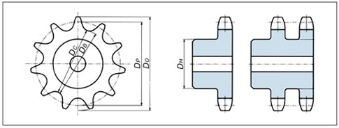
- D P = Pitch diameter
- D O = standard outer diameter
- D B = tooth root diameter
- D C = tooth root distance
- D H = Maximum hub diameter and maximum groove diameter
- P = chain pitch
- d l = roller outer diameter
- N = number of teeth
- DP = P/sin 180°N
- DO = P (0.6 + cot 180°N)
- DB = DP - dl
- D C = D B [for even number of teeth]
- D C = D P cos 90°N-d l [for odd number of teeth]
- DH = P (cot 180°N - 1) - 0.76
Tooth specifications
1. Tooth profile
Our sprocket teeth are machine cut using the JIS standard S tooth profile.
Some parts also use JIS standard U-tooth profiles.
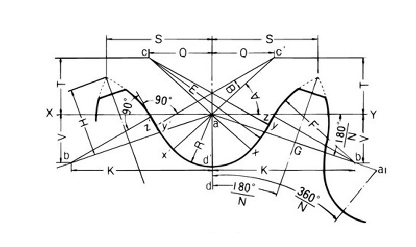
S tooth profile
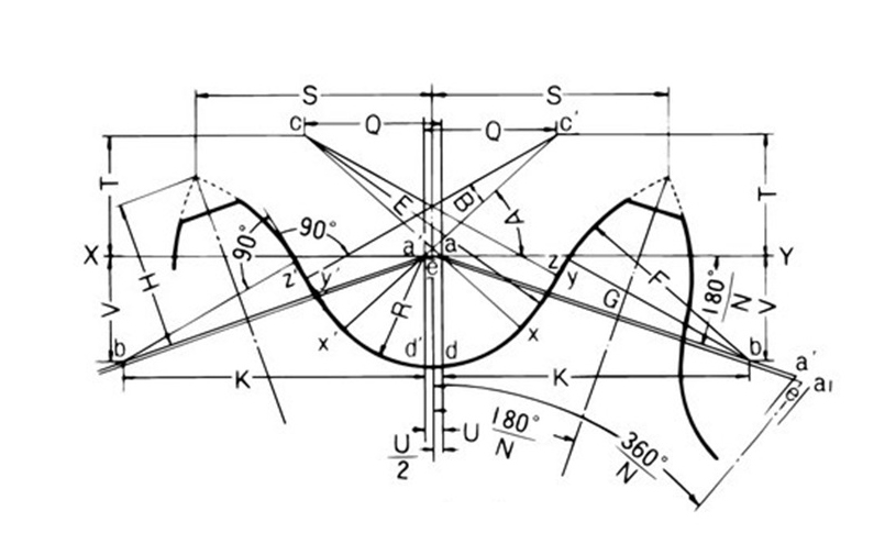
U-tooth profile
- pa = p(1 + DS - dlDP)
- DS = 2R = 1.005dl + 0.076
- U = 0.07(p - dl) + 0.051
- R = DS/2 = 0.5025dl + 0.038
- A = 35° + 60°/N
- B = 18° - 56°/N
- ac = 0.8dl
- Q = 0.8dl cos(35° + 60°/N)
- T = 0.8dl sin(35° + 60°/N)
- E = cy = 1.3025dl + 0.038
- xy = (2.605dl + 0.076) sin(9° - 28°/N)
- yz = dl[1.4 sin (17° - 64°/N) - 0.8 sin(18° - 56°/N)]
- G = ab = 1.4d l
[Point b is on the line that makes an angle of 180°/N with line XY from point a on line XY.] - K = 1.4d l cos180°/N
- V = 1.4dl sin180°/N
- F = dl [0.8 cos (18° - 56°/N)+ 1.4 cos(17° - 64°/N) - 1.3025] - 0.038
-
[S tooth profile is U = 0.]
- S = pa2 cos180°/N + H sin180°/N
- Outer diameter when the tooth tip is pointed = pa cot180°/N + 2H
- Maximum pressure angle = x a b = 35° - 120°/N
- Minimum pressure angle = x a b - B = 17° - 64°/N
- Mean pressure angle = 26° - 92°/N
N = number of teeth, d l = roller outer diameter, DP = pitch circle diameter, p = chain pitch, pa = tooth pitch (a - a 1 for S tooth profile, e - e 1 for U tooth profile)
2. Teeth and width dimensions
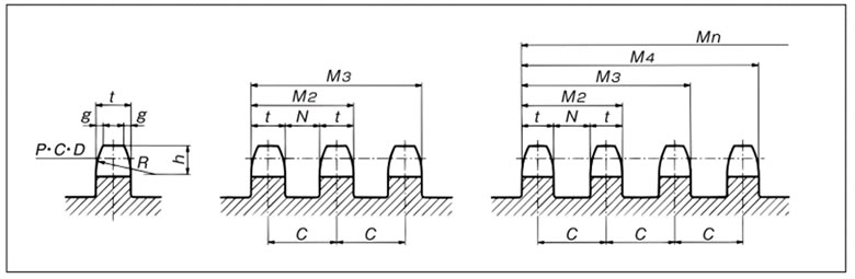
| Size | Each strand | t (max) | C 2 or more strands |
Double strand / Triple strand | 4 or more strands | |||||||||||
|---|---|---|---|---|---|---|---|---|---|---|---|---|---|---|---|---|
| g (reference) |
h | R (minimum) |
Single strand | Double / triple strand | 4 or more strands | M2 | M3 | N | M2 | M3 | M4 | M5 | M6 | N | ||
| RS11 | 0.5 | 1.9 | 4.0 | 1.6 | - | - | - | - | - | - | - | - | - | - | - | - |
| RS15 | 0.6 | 2.4 | 5.1 | 2.0 | - | - | - | - | - | - | - | - | - | - | - | - |
| RS25 | 0.8 | 3.2 | 6.8 | 2.9 | 2.8 | 2.8 | 6.4 | 9.2 | 15.6 | 3.6 | 9.2 | 15.6 | 22.0 | 28.4 | 34.8 | 3.6 |
| RS35 | 1.2 | 4.8 | 10.1 | 4.4 | 4.3 | 4.2 | 10.1 | 14.4 | 24.5 | 5.8 | 14.3 | 24.4 | 34.5 | 44.6 | 54.7 | 5.9 |
| RS41 | 1.6 | 6.4 | 13.5 | 5.8 | - | - | - | - | - | - | - | - | - | - | - | - |
| RS40 | 1.6 | 6.4 | 13.5 | 7.3 | 7.1 | 7.0 | 14.4 | 21.5 | 35.9 | 7.3 | 21.4 | 35.8 | 50.2 | 64.6 | 79.0 | 7.4 |
| RS50 | 2 | 7.9 | 16.9 | 8.9 | 8.7 | 8.6 | 18.1 | 26.8 | 44.9 | 9.4 | 26.7 | 44.8 | 62.9 | 81.0 | 99.1 | 9.5 |
| RS60 | 2.4 | 9.5 | 20.3 | 11.9 | 11.7 | 11.4 | 22.8 | 34.5 | 57.3 | 11.1 | 34.2 | 57.0 | 79.8 | 102.6 | 125.4 | 11.4 |
| RS80 | 3.2 | 12.7 | 27.0 | 15.0 | 14.6 | 14.3 | 29.3 | 43.9 | 73.2 | 14.7 | 43.6 | 72.9 | 102.2 | 131.5 | 160.8 | 15.0 |
| RS100 | 4 | 15.9 | 33.8 | 18.0 | 17.6 | 17.2 | 35.8 | 53.4 | 89.2 | 18.2 | 53.0 | 88.8 | 124.6 | 160.4 | 196.2 | 18.6 |
| RS120 | 4.7 | 19 | 40.5 | 24.0 | 23.5 | 23.0 | 45.4 | 68.9 | 114.3 | 21.9 | 68.4 | 113.8 | 159.2 | 204.6 | 250.0 | 22.4 |
| RS140 | 5.5 | 22.2 | 47.3 | 24.0 | 23.5 | 23.0 | 48.9 | 72.4 | 121.3 | 25.4 | 71.9 | 120.8 | 169.7 | 218.6 | 267.5 | 25.9 |
| RS160 | 6.3 | 25.4 | 54.0 | 30.0 | 29.3 | 28.7 | 58.5 | 87.8 | 146.3 | 29.2 | 87.2 | 145.7 | 204.2 | 262.7 | 321.2 | 29.8 |
| RS180 | 7.1 | 28.6 | 60.8 | 33.7 | 33.0 | 32.3 | 65.8 | 98.8 | 164.6 | 32.8 | 98.1 | 163.9 | 229.7 | 295.5 | 361.3 | 33.5 |
| RS200 | 8 | 31.8 | 67.5 | 36.0 | 35.2 | 34.4 | 71.6 | 106.8 | 178.4 | 36.4 | 106.0 | 177.6 | 249.2 | 320.8 | 392.4 | 37.2 |
| RS240 | 9.5 | 38.1 | 81.0 | 45.0 | 44.0 | 43.1 | 87.8 | 131.8 | 219.6 | 43.8 | 130.9 | 218.7 | 306.5 | 394.3 | 482.1 | 44.7 |
Maximum sprocket hub diameter and typical maximum shaft bore diameter
| Size | RS25 | RS35 | RS40・41 | RS50 | RS60 | RS80 | RS100 | RS120 | RS140 | RS160 | RS180 | RS200 | RS240 | |||||||||||||
|---|---|---|---|---|---|---|---|---|---|---|---|---|---|---|---|---|---|---|---|---|---|---|---|---|---|---|
| chain pitch |
6.35 | 9.525 | 12.70 | 15.875 | 19.05 | 25.40 | 31.75 | 38.10 | 44.45 | 50.80 | 57.15 | 63.50 | 76.20 | |||||||||||||
| Number of teeth | Hub diameter |
Maximum shaft bore diameter |
Hub diameter |
Maximum shaft bore diameter |
Hub diameter |
Maximum shaft bore diameter |
Hub diameter |
Maximum shaft bore diameter |
Hub diameter |
Maximum shaft bore diameter |
Hub diameter |
Maximum shaft bore diameter |
Hub diameter |
Maximum shaft bore diameter |
Hub diameter |
Maximum shaft bore diameter |
Hub diameter |
Maximum shaft bore diameter |
Hub diameter |
Maximum shaft bore diameter |
Hub diameter |
Maximum shaft bore diameter |
Hub diameter |
Maximum shaft bore diameter |
Hub diameter |
Maximum shaft bore diameter |
| 10 | 13 | 3.2 | 19 | 8.8 | 26 | 14 | 32 | 18 | 39 | 22 | 52 | 32 | 65 | 42 | 78 | 50 | 92 | 60 | 105 | 70 | 118 | 78 | 131 | 88 | 158 | 108 |
| 11 | 15 | 5.6 | 22 | 11 | 30 | 18 | 37 | 22 | 45 | 27 | 60 | 38 | 76 | 50 | 91 | 60 | 106 | 71 | 121 | 80 | 137 | 92 | 152 | 103 | 183 | 126 |
| 12 | 17 | 7.2 | 25 | 13 | 34 | 20 | 43 | 26 | 51 | 31 | 69 | 45 | 86 | 57 | 103 | 69 | 121 | 80 | 138 | 93 | 155 | 106 | 173 | 118 | 207 | 144 |
| 13 | 19 | 8.8 | 28 | 15 | 38 | 22 | 48 | 30 | 57 | 36 | 77 | 51 | 96 | 64 | 116 | 79 | 135 | 91 | 155 | 105 | 174 | 119 | 193 | 132 | 232 | 162 |
| 14 | 21 | 10 | 31 | 17 | 42 | 26 | 53 | 33 | 64 | 41 | 85 | 57 | 107 | 72 | 128 | 85 | 150 | 101 | 171 | 117 | 192 | 132 | 214 | 148 | 257 | 180 |
| 15 | 23 | 12 | 35 | 20 | 46 | 28 | 58 | 37 | 70 | 46 | 93 | 61 | 117 | 80 | 140 | 95 | 164 | 111 | 187 | 129 | 211 | 146 | 235 | 163 | 282 | 199 |
| 16 | 25 | 13 | 38 | 21 | 50 | 31 | 63 | 41 | 76 | 51 | 102 | 68 | 127 | 85 | 153 | 104 | 178 | 122 | 204 | 141 | 229 | 159 | 255 | 179 | 306 | 216 |
| 17 | 27 | 14 | 41 | 24 | 54 | 34 | 68 | 45 | 82 | 53 | 110 | 74 | 137 | 93 | 165 | 112 | 193 | 132 | 220 | 152 | 248 | 173 | 275 | 193 | 331 | 232 |
| 18 | 29 | 16 | 44 | 26 | 59 | 37 | 73 | 49 | 88 | 59 | 118 | 80 | 148 | 100 | 177 | 121 | 207 | 144 | 237 | 165 | 266 | 186 | 296 | 208 | 355 | 252 |
| 19 | 31 | 17 | 47 | 29 | 63 | 41 | 79 | 51 | 94 | 62 | 126 | 84 | 158 | 108 | 189 | 129 | 221 | 153 | 253 | 177 | 284 | 199 | 316 | 224 | 380 | 268 |
| 20 | 33 | 19 | 50 | 30 | 67 | 44 | 84 | 55 | 100 | 66 | 134 | 90 | 168 | 114 | 202 | 140 | 235 | 163 | 269 | 188 | 303 | 213 | 337 | 238 | 404 | 283 |
| 21 | 35 | 20 | 53 | 33 | 71 | 47 | 89 | 59 | 107 | 72 | 142 | 95 | 178 | 122 | 214 | 148 | 250 | 175 | 285 | 200 | 321 | 226 | 357 | 254 | 429 | 303 |
| 22 | 37 | 21 | 56 | 35 | 75 | 50 | 94 | 62 | 113 | 77 | 150 | 101 | 188 | 128 | 226 | 157 | 264 | 185 | 302 | 212 | 339 | 239 | 377 | 266 | 453 | 318 |
| 23 | 39 | 22 | 59 | 37 | 79 | 51 | 99 | 65 | 119 | 80 | 159 | 109 | 199 | 137 | 238 | 165 | 278 | 196 | 318 | 224 | 358 | 254 | 398 | 278 | 477 | 338 |
| 24 | 41 | 24 | 62 | 40 | 83 | 54 | 104 | 70 | 125 | 83 | 167 | 113 | 209 | 144 | 251 | 176 | 292 | 205 | 334 | 235 | 376 | 265 | 418 | 294 | 502 | 354 |
| 25 | 43 | 25 | 65 | 42 | 87 | 57 | 109 | 73 | 131 | 88 | 175 | 120 | 219 | 152 | 263 | 184 | 307 | 217 | 351 | 249 | 394 | 275 | 438 | 310 | 526 | 372 |
Note) The maximum bore diameter should be determined by determining the hub thickness according to the operating conditions through general mechanical design.
For reference, the table shows the standard maximum bore diameter for a typical case (sprocket material SS400, JIS keyway). Note that this table was calculated using the JIS hub diameter calculation formula.

