technical data Large size conveyor chain Sprockets Sprocket Structure
1. Basic structure
The tooth profile is subjected to optimal induction hardening hardening treatment, which improves the sprocket's wear resistance and transmission capacity.
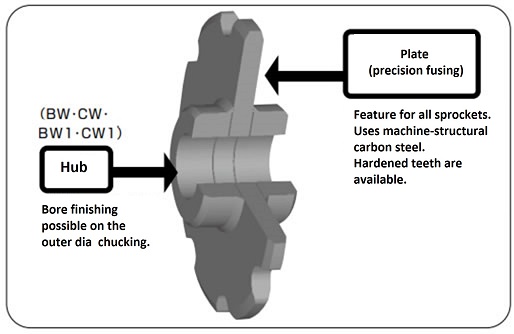
2. Hub format
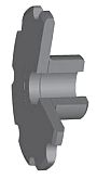
BW type
A hub is welded to one side of the sprocket tooth section.
Applicable
- RF10 size or smaller
- RF205 size or smaller
BW1 type
The hub is inserted into the toothed section of the sprocket, forming a single hub that is welded from both sides.
Applicable
- RF12 size or larger
- RF6205 size or larger
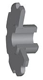
CW type
This type has hubs welded to both sides of the sprocket tooth section.
Applicable
- RF10 size or smaller
- RF205 size or smaller

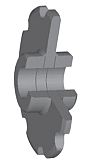
CW1 type
The hub is inserted into the toothed section of the sprocket, forming a double hub that is welded from both sides.
Applicable
- RF12 size or larger
- RF6205 size or larger
3. Tooth type
1. Shape
S1: Tooth tip is circular
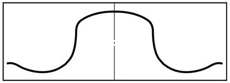
S2: Flat tooth tip (shaded area is cut)
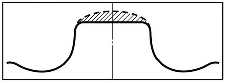
Note: The S2 tooth profile is used for chains with K attachments where the S1 tooth profile may cause interference between the slats and the sprocket outer diameter. Please consult us if you wish to use a special chain or a chain with top rollers.
2. Specifications
- ・ Standard Series (symbol N)
The teeth are not hardened, making them suitable for applications with light loads and low wear. - -Hardened tooth tip specification (symbol Q)
This is a specification with hardened tooth tips. It is suitable for applications requiring wear resistance or under high load conditions. Please follow the table below to distinguish between Standard Series (N) and hardened tooth tips (Q).
Classification of Standard Series and tooth tip hardening specifications
| Chain specifications | Roller type | Drive side | Driven side | ||
|---|---|---|---|---|---|
| Normal atmosphere | Abrasive atmosphere | Normal atmosphere | Abrasive atmosphere | ||
| DT Series DTA Series |
S | Q | Q | N | Q |
| R | N | Q | N | N | |
| F | N | Q | N | N | |
| AT Series ATA Series |
S | Q | Q | N | Q |
| R | Q | Q | N | Q | |
| F | Q | Q | N | Q | |
The above is a classification based on general usage conditions. Please contact us if you are using the product in an especially abrasive environment or under high load conditions.
4. Shaft bore finishing additional specifications
To enable the completion of tedious hole processing in a Quick delivery, the shaft hole dimensions are processed to the following specifications. Please note that setscrews are not included.
Standard shaft hole processing specifications
| Shaft bore tolerance | Keyway width tolerance | Tapping |
|---|---|---|
| H8 | JIS B1301-1996 Normal type Js9 |
Above the keys and at 120° intervals Tapped in two places |
| Old JIS B1301-1959 2 types E9 |
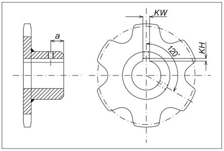
Phase of keyway and tooth tip
The keyway is machined so that the center of the sprocket tooth is aligned with the center of the keyway. If you wish to use chains in parallel, please contact us.
Keyway and tap specifications and dimensions
| JIS standard key, keyway width tolerance Js9 | |||
|---|---|---|---|
| Applicable shaft hole diameter | Keyway width KW |
Keyway Depth KH |
Tap Size MX |
| Over 22 and under 30 | 8 | 3.3 | M6 |
| Over 30 and under 38 | 10 | 3.3 | M8 |
| Over 38 and under 44 | 12 | 3.3 | |
| Over 44 and under 50 | 14 | 3.8 | |
| Over 50 and under 58 | 16 | 4.3 | M10 |
| Over 58 and under 65 | 18 | 4.4 | |
| Over 65 and under 75 | 20 | 4.9 | M12 |
| Over 75 and under 85 | 22 | 5.4 | |
| Over 85 and under 95 | 25 | 5.4 | M16 |
| Over 95 and under 110 | 28 | 6.4 | |
| Over 110 and under 130 | 32 | 7.4 | M20 |
| Over 130 and under 150 | 36 | 8.4 | |
| Over 150 and under 170 | 40 | 9.4 | |
| Over 170 and under 200 | 45 | 10.4 | M24 |
| Over 200 and under 230 | 50 | 11.4 | |
| Old JIS Type 2 Key Keyway Width Tolerance E9 | |||
|---|---|---|---|
| Applicable shaft hole diameter | Keyway width KW |
Keyway Depth KH |
Tap Size MX |
| Over 20 and under 30 | 7 | 3 | M6 |
| Over 30 and under 40 | 10 | 3.5 | |
| Over 40 and under 50 | 12 | 3.5 | M8 |
| Over 50 and under 60 | 15 | 5 | |
| Over 60 and under 70 | 18 | 6 | M10 |
| Over 70 and under 80 | 20 | 6 | M12 |
| Over 80 and under 95 | 24 | 8 | |
| Over 95 and under 110 | 28 | 9 | M16 |
| Over 110 and under 125 | 32 | 10 | M20 |
| Over 125 and under 140 | 35 | 11 | |
| Over 140 and under 160 | 38 | 12 | |
| Over 160 and under 180 | 42 | 13 | |
| Over 180 and under 200 | 45 | 14 | M24 |
| Over 200 and under 224 | 50 | 15.5 | |
| Over 224 and under 250 | 56 | 17.5 | |
If you require processing specifications other than those listed above, please let us know the following information.
- ・Shaft hole shape, diameter, tolerance
- ・Keyway type, dimensions, tolerances
- - Tap size and position

