technical data linear actuator Power Cylinder
Installation and Maintenance: T Series
Installation
Installation direction
Horizontal, vertical, tilt, etc.
Installation environment
- All models have a fully enclosed structure that allows them to be used outdoors. However, even outdoor models require an appropriate cover in adverse environments where they are constantly exposed to water or steam, or in places where snow accumulates. Ambient temperatures vary depending on the conditions of use, but they can generally be used within the range of -15 to 40°C. If they are used above 40°C, be sure to protect them with an insulating cover or similar. Never use in a flammable atmosphere. Doing so may result in an explosion or fire. Also, avoid use in locations where they are subject to vibrations or impacts exceeding 1G.
- - When using cabtyre cables or lead wire-equipped models outdoors, be sure to take adequate waterproofing measures.
Installation method
- - Use a trunnion mount or clevis mount to install the main body. Attach the tip with a U-shaped or I-shaped End fitting.
- - For trunnion mounting, apply grease to the trunnion pin and trunnion hole. Also apply grease to the connecting pin of End fitting and the connecting pin when mounting a clevis.
- - If the main body vibrates significantly when the cylinder is activated, please consider using plain bearings or rolling bearings at the connecting parts.
If you require a plain bearing installed in the trunnion hole, please contact us. - - If the trunnion pin or the connecting pin of the clevis and End fitting faces vertically (when the cylinder is laid on its side) and the main body oscillates, take measures to prevent wear such as inserting plain bearing material into the trunnion hole or the side of the clevis fitting or End fitting.
Figure 1 Installation method
Trunnion Mount
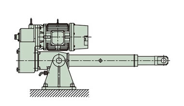
Clevis Mount
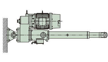
*For mounting hardware, please refer to the options section.
manual operation
To adjust the stroke manually, release the brake on the brake-equipped motor, then turn the manual handle shaft of the reduction section with an adjustable wrench or socket wrench.
| caveat |
If a load is applied to the rod, remove the load before releasing the brake. |
|---|
Please refer to the standard model list (here) for the rod travel distance per rotation of the manual shaft.
Rod rotation prevention
- 1. The rod generates a rotational force (see here) as a result of the thrust, so it is necessary to prevent rotation. The rod rotational force at rated thrust is listed in the model list. In most cases, it is possible to prevent rotation by attaching the end of the rod to the driven machine.
- 2. When moving the tip freely or when attaching a pulley to pull a rope, etc., it is usually necessary to prevent the rod from rotating. If you require Power Cylinder with a rotation stopper, please contact us. Note that the LS rod of the external limit switch unit cannot be used to prevent rotation.
Lateral load on the rod
Install the rod so that no bending load (lateral load) is applied to it.
If a load is applied perpendicular to the rod (lateral load) or in an eccentric load direction (eccentric load), take the following measures.
(1) Lateral load: Install guide rollers on the rod (Fig. 3).
Figure 3 Lateral load
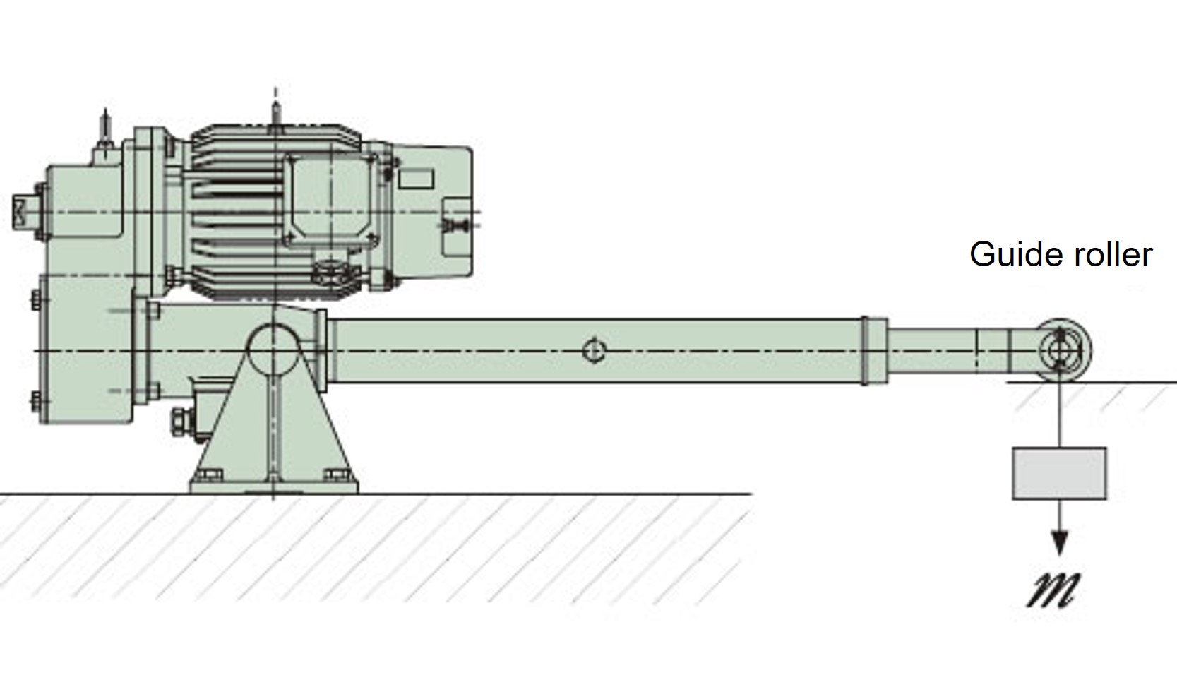
To avoid applying a lateral load directly to the rod, provide guide rollers, etc.
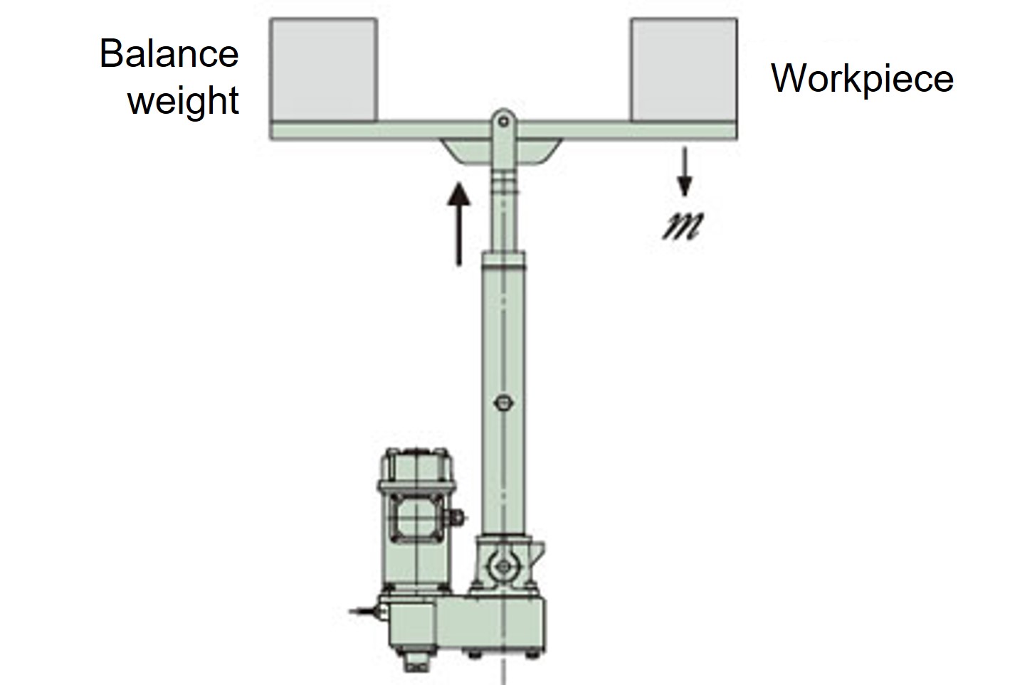
(2) Eccentric load: Use a balance weight, etc. (Fig. 4)
Figure 4 Eccentric load
If an eccentric load is applied, provide a balance weight or similar.
*A separate guide is required for this layout.
About Megger testing
This cylinder is strictly prohibited from Megger testing as it may damage the built-in power module. However, if you wish to perform Megger testing on the external circuit, please remove the brake wiring from the terminal box.
Stroke adjustment external LS (optional) setting
- - An option to attach a limit switch to Power Cylinder body is available, so please use it.
- - Use limit switches to regulate both ends of the stroke.
- ・Please use within the stroke range. If the stroke is exceeded, damage may occur.
- - When adjusting the limit switch, please take into account the coasting distance (here).
- - When using at 100% nominal stroke, set the limit switch so that the cylinder stops within the XA dimension in the dimension table.
- - When operating two or more Power Cylinder at the same time, install limit switches at the upper and lower limits of each cylinder.
- ・Never adjust the C-type thrust detection limit switch yourself, as this may result in a large difference in the thrust detection setting value.
- ・The high-speed type (H speed) of Power Cylinder T series has a long coasting distance, so there is a possibility that the striker will go over the limit switch. For this reason, be sure to operate the limit signal in the control circuit with self-holding.
- Stroke-adjustable external LS (optional) mounted vertically (stroke 300 mm or less)...The connector of the external LS protrudes below the trunnion mounting base surface (Fig. 5).
Fig. 5 Stroke adjustment external LS (option) vertical installation
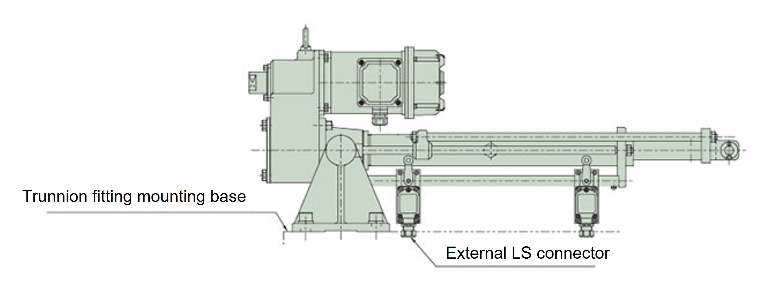
Please take into consideration the mounting base as cable wiring is required.
maintenance
Ball screw lubrication
Ball screw is pre-lubricated with grease, so use it as is. Use Tables 1 and 2 as a guide for adding grease. To grease Ball screw screw, remove the greasing port bolt on the outer cylinder, advance the rod a full stroke, apply grease to the outer circumference of the screw with a grease gun, and then move it back and forth within the stroke range you will be using. Repeat this action 2 to 3 times.
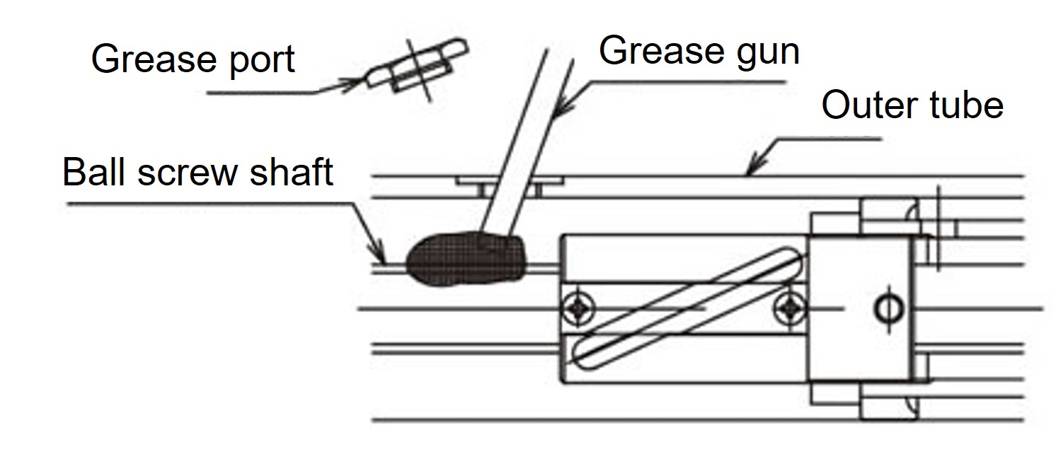
The total amount of grease to be applied at one time is approximately 10 to 15 g per 100 mm of stroke (T250 to T4000).
| caveat |
Never insert your fingers into the grease port. |
|---|
Table 1 Recommended grease (Be sure to use EP (extreme pressure) grease.)
| Usage category | Company Name | Grease name |
|---|---|---|
| Ball screw | Tsubakimoto Chain Co., Ltd. | JWGS100G |
| Idemitsu Kosan Co., Ltd. | Daphne Eponex SR No.2 *1 | |
| Nippon Grease Co., Ltd. | Nigroove EP-2K | |
| EXXON MOBILE | Mobilux EP No.2 | |
| Cosmo Oil Lubricants Co., Ltd. | Cosmo Grease NEW Dynamax EP No.2 | |
| Shell Lubricants Japan K.K. | Shell Gaddus S2 V220 J 2 (EP) *2 |
*1 Grease pre-packaged at the time of shipment.
*2 Former name: Shell Albania EP Grease 2
Note: JWGS100G is sold separately in a 100g container. (See here.)
*The product names listed above are trademarks or registered trademarks of the respective companies.
Ideal for maintenance of Linipower Jack and Power Cylinder!
 (100g included)
形番:JWGS100G
Table 2. Grease cycle
| Frequency of use | Grease Cycle |
|---|---|
| 1001 round trips/day or more | Every 1 to 3 months |
| 501-1000 round trips/day | Every 3 to 6 months |
| 101-500 round trips/day | Every 6 months to 1 year |
| ~100 round trips/day or less | Every 1 to 1.5 years |
*The values in the table above are intended to allow for longer use, and do not indicate the lifespan.
Greasing the reducer
The gears and bearings in the reduction section are pre-lubricated with grease and are therefore not required to be lubricated.
Initial grease application to reducer
- Gear case section: Daphne Eponex SR No.1
- Planetary reduction part: Moly gear grease No.1

