technical data linear actuator Power Cylinder
Important points to note when selecting (Eco Series/CDS type)
- ・Standard cylinders do not have a rotation prevention mechanism. If you wish to use the tip in a free state, please select the rod rotation prevention specification (optional).
In addition, if a magnetic sensor is included (optional), the rod must be designed to prevent rotation. - ・Please refer to this table of allowable start counts to see if the start count of the selected cylinder is within the allowable value.
- - When using this cylinder for pushing or pulling and stopping, the strength of the mating device must be 300% or more of the rated thrust.
- ・ Power Cylinder are designed for indoor use. To avoid problems such as rust, please store them in a good indoor environment. Be careful of humidity. Installing them in a place with sudden temperature changes will cause condensation, which may lead to malfunctions or rust, so please be careful.
- - Do not store or use in a corrosive atmosphere. Also, do not use in a flammable atmosphere.
- - Do not use the product in a sealed container or other location where heat dissipation cannot be expected, as this may cause a malfunction.
Precautions for installation (Eco Series, CDS type)
- - Use a trunnion mount or flange mount to install the main body. If using a trunnion mount that involves oscillation, select an I-shaped or U-shaped End fitting End fitting
- - If a lateral load is applied, provide a guide to prevent direct lateral load or bending moment.
- - When installing with a trunnion mount, it can be installed horizontally or vertically.
- - When installing with a flange mount, install it vertically (see the diagram on the right).
- ・When using with Long travel length and in a horizontal position, separately support the bottom end of the frame as shown in the diagram on the right. In this case, do not fix the frame and support base together.
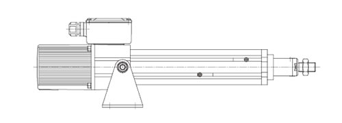
Trunnion Mount
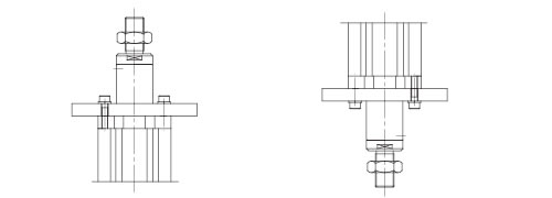
Flange Mount

Frame end support (cannot be fixed)
Precautions for use (Eco Series, CDS type)
- ・The motor stops when the push or pull function is stopped, but the terminal block remains energized. If you open the terminal box to perform work, be sure to turn off the main power.
- - To manually adjust the stroke, remove the cap bolt on the non-load side of the motor and rotate the manual shaft with a flat-head screwdriver. However, this operation will be performed with the brake applied, so please use this only in an emergency. Also, be sure to remove the load when operating manually.
- ・Never use an inverter. This cylinder detects overcurrent using the CDS built into the terminal box, stops the motor, and controls Pressing force, so using an inverter will damage the CDS circuit.
- ・ Megger testing is strictly prohibited for this cylinder. It may damage the built-in CDS. When performing Megger testing on an external circuit, remove all terminals from the terminal box.
- - When switching between forward and reverse, allow an interval of at least 0.2 seconds.
- - The temperature around the motor may rise significantly during operation and immediately after stopping, so never touch the area around the motor.
Reference circuit diagram
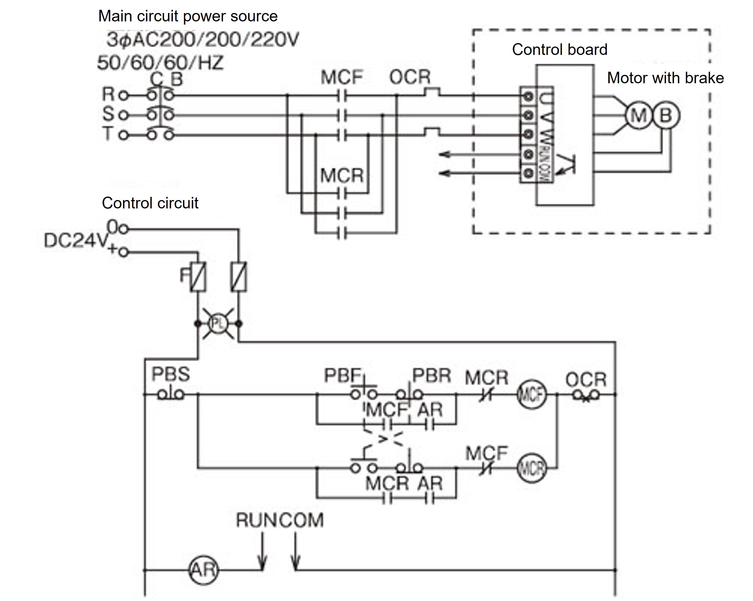
NOTE:
- 1. This is a single-acting circuit diagram. In this circuit diagram, both straight and parallel motors move forward using the PBF.
- 2. When the cylinder advances due to the PBF and hits a wall at the stroke end or midway, it generates Pressing force and automatically stops. When retracting, the cylinder retreats due to the PBR and stops in the same way as on the forward side. The circuit should turn off MCF and MCR every time the cylinder stops.
- 3. An output signal can be taken from the RUN/COM terminals on the cylinder terminal block while the cylinder is operating.
Open collector output MAX.50mA DC30V
Use a coil current of 50mA DC or less for the AR relay. - 4. Use an electromagnetic contactor with a contact capacity equivalent to or greater than the Fuji Electric SC-O.
- 5. Brake motor current value (brake is internally wired)
Model number Motor rated current (A) Motor restraint current value (A) 200V 50Hz 200V 60Hz 220V 60Hz 200V 50Hz 200V 60Hz 220V 60Hz LPE025HT(HK) 0.6 0.6 0.6 1.0 0.9 1.0 LPE050LT(LK) 0.6 0.6 0.6 1.0 0.9 1.0 LPE050HT(HK) 1.1 1.1 1.1 2.1 1.9 2.1 LPE100LT(LK) 1.2 1.3 1.2 2.1 1.9 2.1
Note: The motor rated current value includes the brake current (0.11A) and is the value for the U and W phases on the cylinder terminal box. Please note that this is different from the current value on the motor nameplate.

