technical data Mechanical protector TG Sensor Installation
- The detection distance of the TG sensor is 2.0 mm for the AC type TGS12 and 1.5 mm for the DC type TGS8DN. Set the dimensions (s,t) in the table below with Shock Guard not tripped, and confirm that the TG sensor is in a non-detection state (the operation indicator light on the side is lit).
- Next, trip Shock Guard. Then, while rotating the tripped Shock Guard by hand, confirm that the TG sensor is in the detection state (the operation indicator light on the side is off) and that there is no interference with the sensor plate, and then reset Shock Guard.
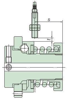
| s | t | Sensor plate amount of movement |
||
|---|---|---|---|---|
| AC type TGS12 |
DC type TGS08DN |
|||
| TGB08-L, M, H | 17.9 | 19.2 | 1.2 | 0.9 |
| TGB12-L, M, H | 21.8 | 22.7 | 1.0 | |
| TGB16-L, M, H | 26.5 | 27.5 | 1.2 | |
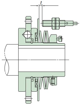
| t | Sensor plate amount of movement |
||
|---|---|---|---|
| AC type TGS12 |
DC type TGS08DN |
||
| TGB20-H | 2.0~3.8 | 2.0~3.2 | 1.8 |
| TGB30-L, H | 2.2~4.0 | 2.2~3.4 | 2.0 |
| TGB50-L, M, H | 2.9~4.7 | 2.9~4.1 | 2.7 |
 Installation Diagram TGB70-130
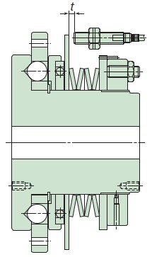
| t | Sensor plate amount of movement |
||
|---|---|---|---|
| AC type TGS12 |
DC type TGS08DN |
||
| TGB70-H | 3.5~5.3 | 3.5~4.7 | 3.3 |
| TGB90-L, H | 5.6~7.4 | 5.6~6.8 | 5.4 |
| TGB110-L, H | 6.2~8.0 | 6.2~7.4 | 6.0 |
| TGB130-L, H | 6.8~8.6 | 6.8~8.0 | 6.6 |
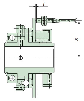
| s | t | Housing movement | ||
|---|---|---|---|---|
| AC type TGS12 |
DC type TGS08DN |
|||
| TGE17 | 35.5 | 34 | 2.0~2.4 | 1.6 |
| TGE25 | 48 | 2.4~2.8 | 2.0 | |
| TGE35 | 60 | 2.8~3.2 | 2.4 | |
| TGE50 | 80 | 3.6~4.0 | 3.2 | |
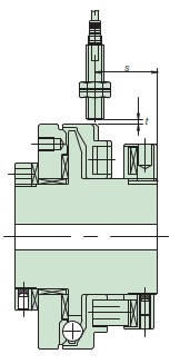
| s | t | Plate displacement | ||
|---|---|---|---|---|
| AC type TGS12 |
DC type TGS08DN |
|||
| TGX10 | 28.8 | 29.9 | 1.2 | 1.4 |
| TGX20 | 27.1 | 28.3 | 1.6 | |
| TGX35 | 28.2 | 29.5 | 2.0 | |
| TGX50 | 34.4 | 35.6 | 2.6 | |
| TGX70 | 33.4 | 34.5 | 3.5 | |
Note)
The TG sensor, which is attached to Shock Guard can only be mounted in the radial direction, as shown in the left diagram.
Installation diagram TGX10-C to 70-C
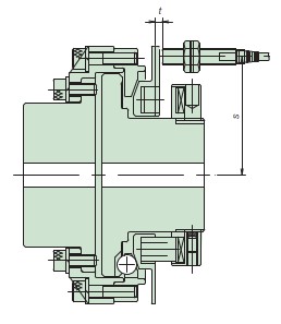
| s | t | Plate displacement | ||
|---|---|---|---|---|
| AC type TGS12 |
DC type TGS08DN |
|||
| TGX10-C | 36.5 | 2.1~3.3 | 2.1~2.8 | 1.3 |
| TGX20-C | 45 | 2.4~3.6 | 2.4~3.1 | 1.6 |
| TGX35-C | 59 | 2.7~3.9 | 2.7~3.4 | 1.9 |
| TGX50-C | 83 | 3.2~4.4 | 3.2~3.9 | 2.4 |
| TGX70-C | 105 | 4.1~5.3 | 4.1~4.8 | 3.3 |
Note)
For TG sensors attached to coupling-type systems, horizontal orientation is recommended, as shown in the left diagram.
Please contact us if you require radial mounting.
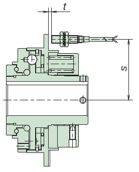
| AC type TGS12 DC type TGS8DN |
Housing movement | ||
|---|---|---|---|
| s | t | ||
| TGF20 | 46 | 1.6~2.0 | 1.2 |
| TGF30 | 60 | 2.2~2.6 | 1.8 |
| TGF45 | 78 | 2.6~3.0 | 2.2 |
| TGF65 | 100 | 3.1~3.5 | 2.7 |
| TGF90 | 136 | 5.4~5.8 | 5.0 |