Technical data Coupling Handling
ECHT-FLEX Coupling NES Series
1. Handling of couplings
Please read Instruction Manuals.
The NES series ECHT-FLEX couplings are delivered as fully assembled products (with pre-machined shaft holes), so they can be installed directly onto the device. Please attach them to the shaft as follows:
When installing, be careful not to apply excessive force to the coupling or drop it.
Never loosen the hexagon socket head bolts that secure the disc.
The operating temperature range is -30℃ to 100℃.
2. Mounting the coupling to the shaft
- (1) Wipe off any dirt or oil from the surface of the mounting shaft and the coupling mounting surface with a cloth.
- (2) Center the mounting shaft and install the coupling onto the shaft, making sure to insert the shaft all the way into the end face of the clamp hub.
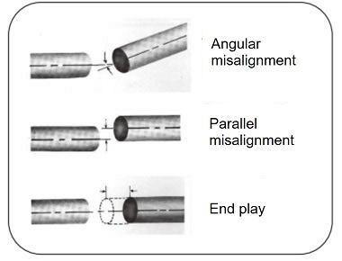
The coupling's allowable angular misalignment (Angular Misalignment), allowable eccentricity (parallel error), and allowable end play (axial displacement) are correlated, and an increase in one will decrease the other, so they must be considered at the same time. Please refer to the following when adjusting the centering.
If the coupling is a spacer type
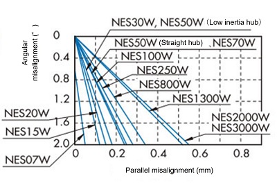
First, convert the eccentricity (parallelism error) into angular deviation (Angular Misalignment) using Graph 1.
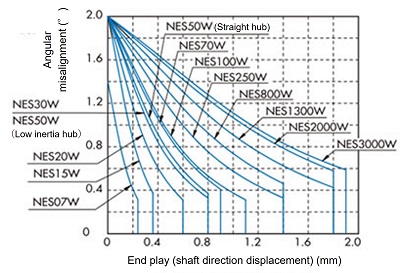
Add the converted value and the declination (Angular Misalignment) together and apply it to the declination (Angular Misalignment) in (Graph 2).
Adjust the centering so that it falls within the range of the graph for each size.
(Graph 1) Spacer type
(Graph 2) Spacer type
When the coupling is a single type
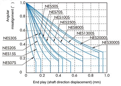
The single type has an extremely small absorption capacity for eccentricity (parallelism error), so centering should be done mainly by adjusting the angular misalignment (Angular Misalignment) and end play (axial displacement).
(Graph 3) shows the correlation between the allowable misalignment angle (Angular Misalignment) and allowable end play (axial displacement) of a coupling.
Please adjust the centering so that it falls within the range of the graph for each size.
- (3) With the clamp bolt loose, check that the installed coupling can move with light force in the rotational and axial directions. If it does not move smoothly, readjust the centering in (2).
- (4) Tighten the clamp bolts according to the tightening torque in the table below.
(Graph 3) Single type
| Model number | NES07 | NES15 | NES20 | NES30 | NES50 | NES70 | NES100 | NES250 | NES800 | NES1300 | NES2000 | NES3000 |
|---|---|---|---|---|---|---|---|---|---|---|---|---|
| Clamp bolt size |
M2 | M2 | M2.5 | M2.5 | M3 | M3 | M4 | M4 | M6 | M6 | M8 | M8 |
| Tightening torque N・m {kgf・m} |
0.50 {0.05} |
0.50 {0.05} |
1.0 {0.10} |
1.0 {0.10} |
1.9 {0.19} |
1.9 {0.19} |
3.8 {0.39} |
3.8 {0.39} |
12 {1.22} |
12 {1.22} |
30 {3.1} |
30 {3.1} |

