Technical data Coupling Handling
ECHT-FLEX Coupling NER Series
This describes the general handling of ECHT-FLEX Coupling NER series. For details, please refer to Instruction Manuals attached to the product.
1. Installing the hub on the shaft
Precautions
- *1 Check the coupling components against the component list in Instruction Manuals.
- *2 The center unit is optimally assembled at the factory. Please use it as is without disassembly.
- *3 Do not apply large forces, especially in the axial direction, to the center unit. This may cause the disc to be fixed in a bent state, impairing performance.
Installation Procedure
- (1) Check that there are no burrs, scratches, dirt, rust, etc. on the drive shaft, driven shaft, and inner diameter of the hub, and wipe off any dirt or oil.
- (2) Attach the hubs to each shaft. For press fit, heat the hubs evenly with heated oil (below 150°C) and quickly attach them to the designated positions on the shafts.
- (3) For the flange face-to-face dimension of the hub, refer to the next section, "2. Centering (1) Adjusting the flange face-to-face dimension (J)."
2. Centering
The higher the initial centering accuracy of the coupling, the less eccentric rotational stresses will be generated during use.
Bearing wear, settlement of the installation surface, changes in condition due to temperature, changes during use due to vibration, etc. will shorten the life of your equipment and couplings.
Please adjust it periodically by following the steps below.
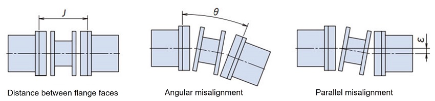
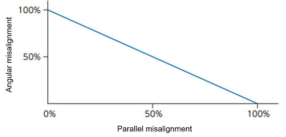
The flange face dimensional error, allowable angular misalignment, and eccentricity of a coupling are correlated, and as one increases the other decreases, they must be considered simultaneously.
Be sure to initially center it to the recommended value below.
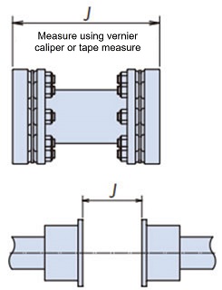
(1) Adjustment of flange face-to-face dimension (J)
Measure the overall length of the center unit and use this value as the J dimension.
(Depending on the combination of component tolerances, the overall length of the center unit may be longer or shorter than the standard value. In that case, even if the hub is set within J±0.5 mm of the standard dimensions on the drawing, it may be difficult to assemble the center unit.)
Measure the J dimension at four points every 90 degrees, and adjust the hub position so that the average value is within J±0.5 mm. If the drive shaft or driven shaft is a stepped shaft, the adjustment margin may be limited, so please make sure that the J dimension can be adjusted in advance.
(2) Adjustment of the declination angle (θ)
- (a) Fix the dial gauge to one of the hubs as shown in the figure, rotate the hub to find the minimum reading on the dial gauge, and set it to zero.
- (b) Rotate the dial hub 360 degrees and read the declination value.
- (c) Adjust the device by moving it using shims or other tools so that the dial gauge reading falls within the range of the recommended declination values in Table 1.
(3) Eccentricity (ε) adjustment
- (a) Attach a dial gauge to the hub flange as shown in the figure, rotate the hub to find the minimum reading on the dial gauge, and set it to zero.
- (b) Rotate the hub that is fixed with the dial gauge 360 degrees and read the eccentricity value.
- (c) There may be abnormal runout on the outer periphery of the hub at the drilled hole part of the hub. This is because the flange bulged outward when the drilled hole part was machined, so please read the reading while avoiding this part.
- (d) Adjust the equipment by moving it using shims or other means so that the dial gauge reading is within twice the recommended eccentricity value in Table 1 or Table 2.
- (e) If the equipment is moved to adjust the eccentricity, adjust the declination again.

| Model number | Recommended centering value | ||||
|---|---|---|---|---|---|
| Declination | eccentricity ε [mm] |
Flange Face-to-face dimensions J [mm] |
|||
| θ [deg] |
T.I.R. [mm] |
||||
| NER59W | 0.35 | 0.33 | 0.18 | ±0.5 | |
| NER93W | 0.35 | 0.39 | 0.22 | ±0.5 | |
| NER230W | 0.25 | 0.31 | 0.18 | ±0.5 | |
| NER360W | 0.25 | 0.36 | 0.22 | ±0.5 | |
| NER630W | 0.25 | 0.43 | 0.22 | ±0.5 | |
| NER850W | 0.25 | 0.48 | 0.25 | ±0.5 | |
| Model number | Recommended centering value | ||||
|---|---|---|---|---|---|
| Declination | Eccentricity (Calculation formula) ε [mm] |
Flange Face-to-face dimensions J [mm] |
|||
| θ [deg] |
T.I.R. [mm] |
||||
| NER59W | 0.35 | 0.33 | (J-44.4)×0.31×10-2 | ±0.5 | |
| NER93W | 0.35 | 0.39 | (J-50.6)×0.31×10-2 | ±0.5 | |
| NER230W | 0.25 | 0.31 | (J-58.8)×0.22×10-2 | ±0.5 | |
| NER360W | 0.25 | 0.36 | (J-70.0)×0.22×10-2 | ±0.5 | |
| NER630W | 0.25 | 0.43 | (J-76.4)×0.22×10-2 | ±0.5 | |
| NER850W | 0.25 | 0.48 | (J-86.6)×0.22×10-2 | ±0.5 | |
Relationship between declination and eccentricity
3. Center unit installation
- (1) Refer to the component diagram in Instruction Manuals and install the center unit to the hub.
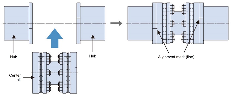
Figure 1. Center unit installation
There are alignment marks (lines) in two places (on one side) on the periphery of the hub and the periphery of the center unit.
Make sure these are in phase.
The center unit has no directionality, so it can be installed facing either left or right.
- (2) Secure the hub and center unit with the positioning bolts and hex socket bolts.
At this time, make sure to insert the positioning bolt (the bolt with the green head) into the drilled hole where the alignment mark (line) is located. It will not fit into any other drilled holes.
Positioning bolts (bolts with green heads) are used in two places on each side, symmetrically at 180° angles (four places per coupling).
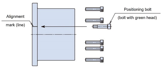
Figure 2. Inserting the positioning bolt and hex socket bolt
Be sure to tighten the positioning bolts and hexagon socket bolts to the "Tightening torque for positioning bolts and hexagon socket bolts" in Table 3.
Table 3. Tightening torque for positioning bolts and hex socket bolts Model number Bolt size Tightening torque
[N・m]NER59W M6 14 NER93W M6 14 NER230W M6 14 NER360W M8 34 NER630W M10 67 NER850W M10 67 - (3) Once assembly is complete, remove the disc protection plate from the disc section.
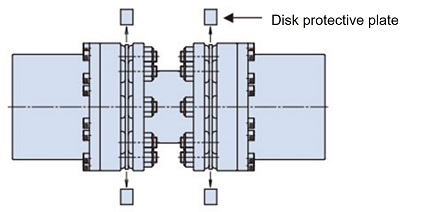
There are four disc protection plates in total, two on each side.
4. Inspection
Recheck the declination and eccentricity after 1-2 hours of operation.
At that time, retighten the positioning bolts and hex socket bolts to the specified torque in Table 3.
Also, check every six months to one year to make sure there are no abnormalities in the parts and that the positioning bolts and hex socket bolts are not loose.
We recommend marking the positioning bolts, hex socket bolts and hubs after installation to check for looseness.
Check that there are no abnormalities in other parts.

