Technical data Coupling Handling
Power Rigid Coupling EPR Series
Installation
Wipe the shaft surface and the inner circumference of the body clean, and apply a thin layer of oil to each part.
1. Mounting shaft diameter tolerance
The tolerance of the shaft diameter when installing the Power Rigid Coupling should be as shown in the table below.
| Mounting shaft diameter | Φ35 | Other than Φ35 |
|---|---|---|
| Recommended Tolerance | +0.010 -0.010 |
h6 or h7 |
Φ35 is the shaft diameter of the servo motor, and the tolerance is (+0.01 to 0).
Therefore, the hole tolerance of the coupling is also adjusted accordingly.
Please note that even if Ball screw screw shaft diameter is Φ35, the hole diameter tolerance for both is the same.
- - The yield point of the mounting shaft material must be 343MPa {35kgf/mm 2} or higher (S45C equivalent or higher).
- - The surface roughness of the shaft must be Ra1.6 or less.
2. Centering
- (1) Attach the coupling to one side of the shaft and tighten the outer ring according to the procedure.
- (2) Leave the outer ring of the other shaft untightened. This shaft can rotate freely within the shaft hole of the coupling.
- (3) Fix the dial gauge to the base (coupling case, etc.) and check the runout of each shaft.
- 1. Place a dial gauge on the outer periphery of the center flange of the coupling body when the shaft is fastened to the coupling.
Rotate this shaft and read the runout, keeping it within 3/100 (Figure 1). - 2. Next, place a dial gauge on the other shaft, rotate this shaft, and read the runout to bring it within 3/100.
- 1. Place a dial gauge on the outer periphery of the center flange of the coupling body when the shaft is fastened to the coupling.
- (4) Check that the runout on both dial gauges is within the specified value, then tighten the other outer ring according to the correct procedure.
- (5) Finally, check the flange runout on the main body with a dial gauge to make sure it is within 3/100.
| Dial gauge on the outer periphery of the main body |
|---|
| Within 3/100 mm |
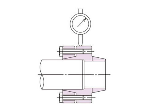
Figure 1
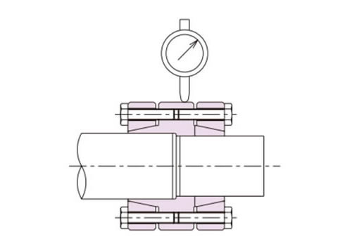
Figure 2
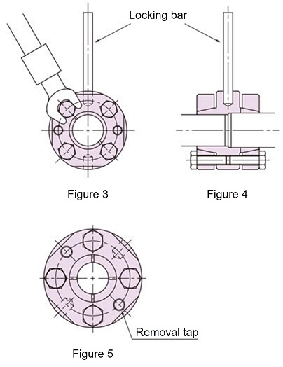
3. Tightening the pressure bolt
When tightening the pressure bolts, first pretighten them by hand, then gradually tighten the diagonal bolts (Fig. 3).
Finally, use a torque wrench to tighten to the specified torque of 16.7 N·m {1.70 kgf·m}.
At this time, place a dial gauge on the outer diameter of the body and tighten the pressure bolt so that the gauge runout is as close to 0 as possible (Fig. 2).
Additionally, if you insert a locking bar into the drilled holes on the outside of the body to secure it in place, the work will be easier (Figure 4).
4. Removal
Loosening the pressure bolt will release the taper lock. If it is stuck, you can remove it by tightening the pressure bolts into the removal taps (2 places) on the outer ring (Figure 5).5. Inspection
After installation, perform a test run to check that there are no abnormalities such as vibrations or strange noises. Also, check that the pressure bolts are not loose.6. Maintenance
Check the installation status once or twice a year. If any abnormalities are found, take action immediately.