technical data Reducer Worm Reducer Handling
This page describes general matters regarding the handling of the EWJ, EWJM(R), EW, EWM(R), SWJ, SWJM(R), SW, SWM(R), and TD series.
For details, please refer to Instruction Manuals attached to the product.
5. Consolidation
5-1. Check the direction of rotation
All worms are right-hand helix. Please check the rotational relationship between the input and output shafts.
5-2. Consolidation
- - When installing a pulley, sprocket, or coupling on the input or output shaft of the reducer, do not apply impact force or excessive thrust load to the shaft.
- - Center accurately. For information on centering accuracy, refer to the catalog or Instruction Manuals for the pulley, sprocket, coupling, etc. you are using.
- - Shaft eccentricity and radial or axial loads exceeding the allowable values can cause vibration and noise, and also shorten the life of gears, bearings, and shafts.
5-3. Motor installation (applies to EWJM, EWM, SWJM, and SWM series motor handling code: Y)
- - When assembling the motor, the input shaft is hollow and no coupling is used to connect it to the reducer.
- ・The input shaft of the reducer is machined with a shaft hole and keyway to match the specified motor capacity. Please use the key that comes with the motor when assembling the motor.
- ・When installing the motor, please follow the steps below and pay attention to safety.
Motor installation instructions
| procedure | Installation Instructions | Precautions |
|---|---|---|
| 1 |
Install the reducer so that the motor can be easily attached. 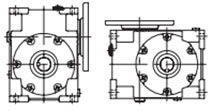
|
When transporting, please take sufficient safety precautions. |
| 2 |
Match the phase of the motor output shaft key and the reducer input shaft keyway. 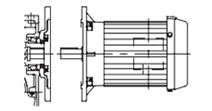
|
When transporting the motor, please take sufficient safety precautions. Make sure to center the shaft completely to prevent eccentricity. |
| 3 |
Gently insert the motor output shaft into the reducer input shaft. 
|
Apply grease to the motor output shaft and reducer input shaft hole as well. Grease brand: Mobil SHC Grease 681WT (manufactured by ExxonMobil) |
| 4 |
Secure the included hexagon socket head bolts to the motor flange completely with spring washers. 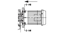
|
Make sure the motor is properly inserted into the reducer before tightening the bolts. Tighten the bolts with a tightening torque that corresponds to their size and strength class. |
- Note: Even if the reducer is the same size, the motor flange diameter will differ depending on the motor capacity. In addition, the shaft hole and keyway processing of the reducer input shaft will also differ.
- Note: When connecting the reducer and motor, use the motor's hanging hook to work safely and carefully.
When the reducer and motor are connected by Jaw-Flex coupling
(Applies to motor handling code Y for EWJM(R)42, EWJM(R)50-70 Double reduction type, and SWJM(R)35-70)
- ・The coupling hub on the reducer side is set (with a key and locking screw) at the time of shipment. Please make sure to check that it has not become loose during transportation, etc.
- - The coupling hub on the motor side is shipped with the shaft hole and keyway machined to match the specified motor capacity.
*A collar for adjusting the motor shaft length is included, so be sure to install it.
Note: When installing the coupling hub on the motor side, use the key and set screws provided with the reducer.
- - Please use the inserts that are included with the shipment.
- ・Motor flange mounting bolts and spring washers are included when shipped. Please check the table below.
| Motor Capacity | 0.1kW | 0.2kW | 0.4kW | 0.75kW | 1.5kW | 2.2kW | 3.7kW | 5.5kW |
|---|---|---|---|---|---|---|---|---|
| Bolt size | M8×25mm | M8×25mm | M8×25mm | M10×30mm | M10×30mm | M12×30mm | M12×30mm | M12×35mm |
| Spring washer | For M8 | For M8 | For M8 | For M10 | For M10 | For M12 | For M12 | For M12 |
| quantity | 4 | 4 | 4 | 4 | 4 | 4 | 4 | 4 |
Motor installation instructions: Please follow the steps below and pay attention to safety when installing the motor.
| procedure | Installation Instructions | Precautions |
|---|---|---|
| 1 |
Install the reducer so that the motor can be easily attached. 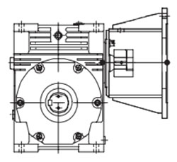
|
When transporting, please take sufficient safety precautions. |
| 2 |
Apply a thin layer of grease to the motor output shaft, insert the input collar, and then attach Jaw-Flex coupling. 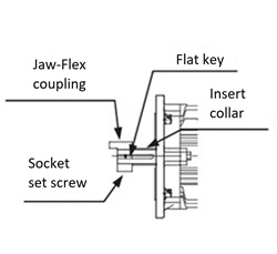
|
When inserting the coupling, do not hit it hard with a hammer or other object. When transporting the motor, please take sufficient safety precautions. |
| 3 |
Insert Jaw-Flex coupling insert into the coupling side of the reducer. 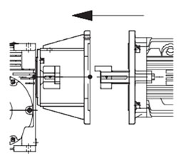
|
When connecting the coupling on the motor side, insert it smoothly into the insert. If it cannot be inserted smoothly due to sticking or other reasons, do not force it in, but align the phase and center again. |
| 4 |
Secure the included hexagon socket head bolts to the motor flange completely with spring washers. 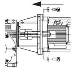
|
Make sure the motor is properly inserted into the reducer before tightening the bolts. Tighten the bolts with a tightening torque that corresponds to their size and strength class. |
Note: When connecting the reducer and motor, use the motor's hanging hook to work safely and carefully.

