technical data Reducer Servo Motor Reducer TERVO Handling
This page describes general information regarding the handling of the TERVO HMTK, GMTK, SWJMK, SWMK, EWJMK, and EWMK series.
For details, please refer to Instruction Manuals attached to the product.
Installation
1. Installation direction
- ・HMTK, GMTK, SWJMK, EWJMK
There are no restrictions on the installation direction. It can be installed horizontally, vertically, or at an angle. - ・SWMK, EWMK
Horizontal installation is standard for reducer sizes 80 and 100. If you require a different installation direction, please specify this when ordering.
Installation
1. Foot mount type
- (1) Use a strong, flat mounting base that is less susceptible to vibrations during operation. After removing any dirt or foreign matter from the mounting surface, secure the base firmly with four bolts.
- (2) When connecting with a coupling, be sure to align the shafts properly. Eccentricity of the shafts will shorten the life of the bearings, gears, and shafts, and will also cause noise and vibration.
- (3) Accurately center the chain or belt, and adjust the tension so that the load on the output shaft does not exceed the specified value.
- (4) When connecting, be careful not to hit the output shaft, coupling, pulley, or sprocket too hard, as this may damage the output shaft bearing.
2. Flange mounting type
- (1) For flange mounting, use a strong, flat flange that is less susceptible to vibrations during operation. After removing any dust or foreign matter from the installation surface, secure it firmly with four bolts.
- (2) When connecting with a coupling, be sure to align the shafts properly. Eccentricity of the shafts will shorten the life of the bearings, gears, and shafts, and will also cause noise and vibration.
- (3) Accurately center the chain or belt, and adjust the tension so that the load on the output shaft does not exceed the specified value.
- (4) When connecting, be careful not to hit the output shaft, coupling, pulley, or sprocket too hard, as this may damage the output shaft bearing.
3. Face mount type
- (1) When installing the product on the machine body, use the taps on the case.
- (2) When connecting with a coupling, be sure to align the shafts properly. Eccentricity of the shafts will shorten the life of the bearings, gears, and shafts, and will also cause noise and vibration.
- (3) Accurately center the chain or belt, and adjust the tension so that the load on the output shaft does not exceed the specified value.
- (4) When connecting, be careful not to hit the output shaft, coupling, pulley, or sprocket too hard, as this may damage the output shaft bearing.
4. Hollow shaft type
4-1. Mounting to the driven shaft
- (1) The hollow shaft inner diameter tolerance is manufactured to JIS H8. The driven shaft should normally be finished to h7, but in the case of large impacts or radial loads, the fit should be slightly tighter, such as js6 or k6.
- (2) When installing the drive shaft, apply molybdenum disulfide grease to the surface of the drive shaft and the inner diameter of the hollow output shaft before inserting.
- (3) If you make and use a jig like the one shown on the right, you can insert it smoothly.
4-2. Fixing to the driven shaft
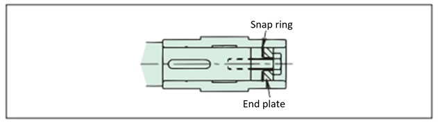
A. When there is a step on the driven shaft
Fabricate an end plate as shown in the diagram below and secure the hollow output shaft and driven shaft in place.
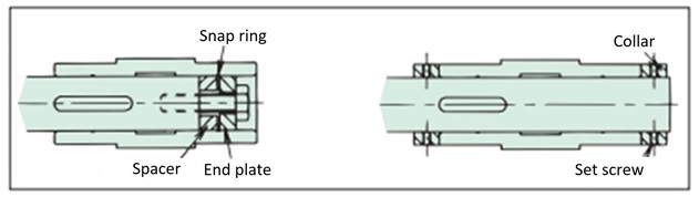
B. Example when there is no step on the driven shaft
There are two fixing methods:
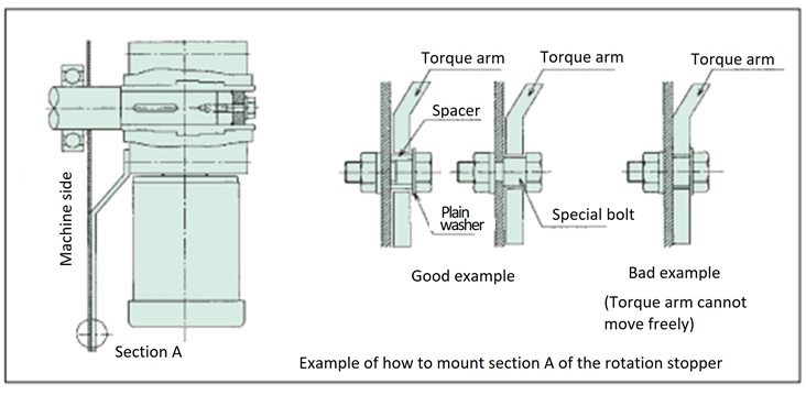
4-3. Torque arm rotation stopper
- (1) Install the torque arm on the driven machine side of the reducer using a hexagon socket head bolt.
- (2) The torque arm's anti-rotation section must have some degree of freedom between the reducer and the driven shaft, and the torque arm must never be fixed with an anti-rotation bolt. If there is no freedom of freedom, it may cause damage to the bearings inside the reducer.
- (3) If the start-up frequency is high or if the motor is repeatedly operated forward and reverse, installing a rubber bushing between the torque arm and the anti-rotation bolt (or spacer) will help to reduce the impact.
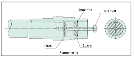
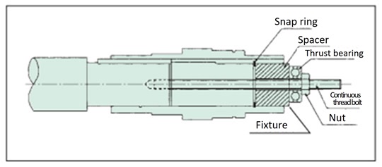
4-4. Removal from the driven shaft
- (1) Remove the driven shaft from the hollow output shaft so that no excess force is applied between the casing and the hollow output shaft.
- (2) If you make and use a jig like the one shown on the right, removal will be smooth.