technical data Reducer Small Gear Motor Selection
If you would like to see the selection procedures and important points, please proceed below.
If you would like to narrow down or tentatively select a product series,
Please click here.
If your usage conditions have been decided and you would like a detailed selection,
Please click here.
Selection example [Conveyor drive]
A and B in the selection example indicate the installation methods shown in the diagram below, A: Foot mount, B: hollow shaft installation.
The selection example is for Hypoid Motor, but Gear Motor and Croise Motor can also be selected according to the installation method.
A: Foot mount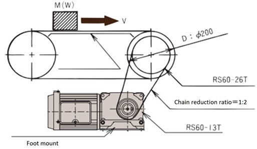
|
B: Hollow shaft mounting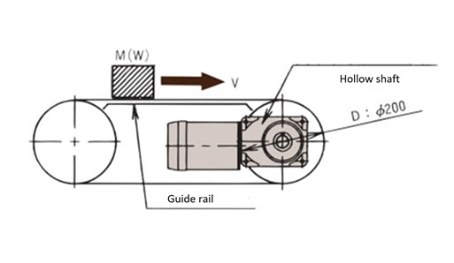
|
|
Selection criteria
|
|
1. Deciding the reduction ratio
Determine the reduction ratio based on the required output shaft rotation speed.
Please refer to the reduction ratio in the characteristics table to determine the ratio.
- A: (1) Calculate the rotational speed (n C) of the conveyor shaft.
nC = V × 1000 D × π = 14 × 1000 200 × π = 22.3 r/min
- (2) Calculate the output shaft rotation speed (n L) of Hypoid Motor.
nL = nC × 2 1 = 44.6 r/min
- (3) Determine the reduction ratio.
From the specifications table on the product page, if we look for an output shaft rotation speed close to 60Hz, 44.6 r/min, it comes out to 45 r/min, with a reduction ratio of 1/40.
- B: (1) Calculate the rotational speed (n C) of the conveyor shaft.
nC = V × 1000 D × π = 14 × 1000 200 × π = 22.3 r/min
- (2) Calculate the output shaft rotation speed (n L) of Hypoid Motor.
nL = nC = 22.3 r/min
- (3) Determine the reduction ratio.
From the specifications table on the product page, if we look for an output shaft rotation speed close to 60Hz, 22.3 r/min, we get 22.5 r/min, which gives a reduction ratio of 1/80.
2. Calculating the output shaft torque
Calculate the required output shaft torque from the load torque.
Depending on the operating conditions, multiply the service factor in Table 1 to obtain the corrected output shaft torque.
- A: (1) Calculate the required torque (T C) of the conveyor shaft.
TC = 9.8μM D 2 × 1 1000 × 1 η = 9.8 × 0.15 × 150 × 200 2000 × 1 0.95 = 23.2N・m
TC = μW D 2 × 1 1000 × 1 η = 0.15 × 150 × 200 2000 × 1 0.95 = 2.37kgf・m
- (2) Convert into Hypoid Motor output shaft torque (TL).
TL = TC × 1 2 × 1 η = 23.2 × 1 2 × 1 0.95 = 12.2N・m
TL = TC × 1 2 × 1 η = 2.37 × 1 2 × 1 0.95 = 1.25kgf・m
- (3) Calculate the output shaft compensation torque (T F).
The service factor in Table 1 is C F = 1 and T F = T L × 1 = 12.2 N m
{T F = T L × 1 = 1.25kgf・m} - (4) Calculate the motor capacity.
According to the specifications table on the product page, the torque of 12.2N・m {1.25kgf・m} at 60Hz with a reduction ratio of 1/40 is 0.1kW.
- B: (1) Calculate the required torque (T C) of the conveyor shaft.
TC = 9.8μM D 2 × 1 1000 = 9.8 × 0.15 × 150 × 200 2000 = 22.1N・m
TC = μW D 2 × 1 1000 = 0.15 × 150 × 200 2000 = 2.25kgf・m
- (2) Hypoid Motor output shaft torque (TL) is equal to the conveyor shaft torque, so TL = TC = 22.1N・m {TL = TC = 2.25kgf・m}
- (3) Calculate the output shaft compensation torque (T F).
The service factor in Table 1 is C F = 1 and T F = T L × 1 = 22.1 N·m {T F = T L × 1 = 2.25 kgf·m}
- (4) Calculate the motor capacity.
According to the specifications table on the product page, the torque of 22.1N・m {2.25kgf・m} at 60Hz with a reduction ratio of 1/80 is 0.1kW.
3. Model number assumptions
From reduction ratio, torque, and quick stop
A: We will check the conditions assuming that Hypoid Motor with brake is HMTA010-22L40RB.
B: We will check the conditions assuming that Hypoid Motor with brake is HMTA010-20H80B.
4. Check the load moment of inertia {load inertia (GD 2)} and start-up frequency
When starting a load with a large moment of inertia (or when stopping if equipped with a brake), a large torque is generated instantaneously, which may cause an unexpected accident, so please consider the method of connection to the load and the moment of inertia of the load {load inertia (GD 2)}.
- A: (1) Calculate the moment of inertia (I C) {load inertia (GD C2)} of the load on the conveyor axis.
IC = MR2 = 150 × 0.12 = 1.5kg・m2
{GDC2 = WD2 = 150 × 0.22 = 6kgf・m2}R = 1 2 D
- (2) Calculate the moment of inertia (I ℓ) {load inertia (GD ℓ2)} equivalent to the motor shaft.
Iℓ = IC × 1 iC2 × 1 iL2 = 1.5 × 1 2 2 × 1 40 2 = 0.23 × 10⁻³kg・m2
GDℓ2 = GDC2 × 1 iC2 × 1 iL2 = 6 × 1 2 2 × 1 40 2 = 0.94 × 10⁻³kgf・m2
- (3) Calculate the inertia ratio (U) with respect to Hypoid Motor.
U = Iℓ IM
U = GDℓ2 GDM2
The motor shaft equivalent moment of inertia (IM) {load inertia (GD M2)} is 0.66 x10 -3 kgf・m 2 {2.64 x10 -3 kgf・m 2}.
U = 0.23 × 10⁻³ 0.66 × 10⁻³ ≒ 0.35
U = 0.94 × 10⁻³ 2.64 × 10⁻³ ≒ 0.36
- (4) Check the startup frequency
From Table 3, the inertia ratio and allowable start frequency, the start frequency is 30 times/hour, which satisfies the conditions.
- B: (1) Calculate the moment of inertia (I C) {load inertia (GD C2)} of the load on the conveyor axis.
IC = MR2 = 150 × 0.12 = 1.5kg・m2
{GDC2 = WD2 = 150 × 0.22 = 6kgf・m2}R = 1 2 D
- (2) Calculate the moment of inertia (I ℓ) (GD ℓ2) equivalent to the motor shaft.
Iℓ = IC × 1 iL2 = 1.5 × 1 80 2 = 0.23 × 10⁻³kg・m2
GDℓ2= GDC2× 1 iL2 = 6 × 1 80 2= 0.94 × 10⁻³kgf・m2
- (3) Calculate the inertia ratio (U) with respect to Hypoid Motor.
U = Iℓ IM
U = GDℓ2 GDM2
The motor shaft equivalent moment of inertia (IM) is 0.66 ×10 -3 kgf・m 2 {2.64 ×10 -3 kgf・m 2}.
U = 0.23 × 10⁻³ 0.66 × 10⁻³ ≒ 0.35
U= 0.94 × 10⁻³ 2.64 × 10⁻³ ≒ 0.36
- (4) Check the startup frequency
From Table 3, the inertia ratio and allowable starting frequency, the starting frequency is 6 times/minute, which satisfies the conditions.
*If you are not satisfied, the reducer may be damaged earlier than expected, so please use a higher model number and check again, or reduce the frequency of use.
- - If the frequency of use cannot be reduced, the lifespan will be limited, so please contact us.
- - If the inertia ratio is large, we recommend using an inverter or similar to start the motor slowly.
5. Check the overhang load (OHL)
When attaching sprockets, gears, belts, etc. to the output or input shaft, please make sure that the overhang load acting on the shaft is less than the allowable overhang load (listed in the characteristics table) of Hypoid Motor being used.
Ask for OHL.
O.H.L = 2000TF × f × Lf DS
- A: If the action position is the center of the shaft length, from Table 4. OHL coefficient f, Equation 1. Action position coefficient L f, and Table 5. Reference length Q,
f = 1 Lf = 1
RS60-13T PCD = 79.6mm
O.H.L = 2000 × 12.2 × 1 × 1 79.6 = 307N
O.H.L = 2000 × 1.25 × 1 × 1 79.6 = 31.4kgf
Check that it is within the allowable OHL. The allowable OHL in the characteristics table is 1617N {165kgf}, which is OK.
- B: Assuming the operating position is at ℓ from the end of the hollow output shaft in the diagram below,
f = 1 Lf = 1
O.H.L = 2000 × 22.1 × 1 × 1 200 = 221N
O.H.L = 2000 × 2.25 × 1 × 1 200 = 22.5kgf
Check that it is within the allowable OHL. The allowable OHL in the characteristics table is 2254N {230kgf}, which is OK.
*If you are not satisfied, try moving the operating position closer to the base of the output shaft, increasing the PCD of the sprocket, or increasing the model number of Hypoid Motor.
6. Deciding on the model number
The next model number is determined based on the installation method, power supply, quick stop conditions, torque, reduction ratio, start frequency, and OHL that are satisfied.
Hypoid Motor with brake
A:HMTA010-22L40RB
B:HMTA010-20H80B

