technical data Reducer Small Gear Motor Selection
technical data for selection
1. Service Factor
All output shaft capacity torque values in the characteristics table are values with Service factor of 1.0.
Select the service factor (Cf) from the table on the right according to the operating time, operating conditions, and load conditions, and calculate the output shaft correction torque.
Table 1. Service Factor: (C F)
| Operating time | 10 hours or less/day | 10 hours or more/day | |
|---|---|---|---|
| Operating status | Intermittent/Continuous | Intermittent/Continuous | |
| Load Condition | Shock-free uniform load | 1 | 1 |
| Light shock load | 1 | 1.2 | |
Note: Please consult us if you plan to use the product under moderate or severe shock loads.
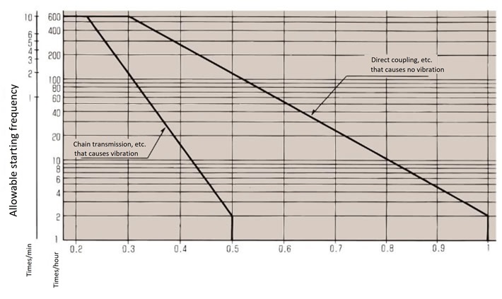
2. Inertia ratio and allowable starting frequency
When starting, an impact torque is generated due to the load inertia (and also when braking if equipped with a brake), which may cause an unexpected accident depending on the load connection method and the magnitude of the load inertia. Therefore, please check the load connection method and load inertia using the following procedure.
- (1) Calculation of the load moment of inertia (I) {load inertia (GD 2)}
- (2) Calculate the moment of inertia of the load (IL) converted to the motor shaft {load inertia (GDL 2)}
- (3) Calculate the inertia ratio (U) with the small gear motor.
U = IL IM
U = GDL2 GDM2
I n {GD M2}: Moment of inertia equivalent to the motor shaft of the small gear motor {Motor shaft equivalent inertia}
- (4) Check whether the allowable start-up frequency is satisfied from Tables 1 and 2.
Table 2. Croise Motor inertia ratio and allowable start frequency
| Load characteristics | Inertia ratio: U | Allowable startup frequency |
|---|---|---|
| If there is no play | 1 0.5 0.2 or less |
4 times/hour 4 times/minute 10 times/minute |
| When there is looseness in the chain, etc. | 0.5 0.3 0.2 or less |
4 times/hour 4 times/minute 10 times/minute |
Note: If conditions other than those in Table 2 apply, please contact us.
Table 3. Gear Motor and Hypoid Motor: inertia ratio and allowable starting frequency
Inertia ratio = Motor shaft equivalent load moment of inertia Motor shaft equivalent Hypoid Motor / Gear Motor motor moment of inertia
3. Check the output shaft overhang load
When mounting a splotch, gear, belt, etc. on the central output shaft, or when mounting using case taps on the hollow shaft, make sure that the overhang load acting on the output shaft is within the allowable OHL of the small gear motor being used.
*When using a heavy-duty toothed belt, add installation tension to the calculation, regardless of the OHL coefficient (f) in Table 4.
Table 4. OHL coefficient f
| Chain | Geared belt | V-belt |
|---|---|---|
| 1.0 | 1.25 | 1.5 |
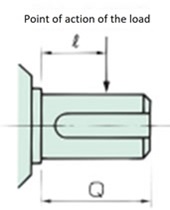
Equation 1. Location of action factor: Lf
| ℓ/Q | 0.25 | 0.38 | 0.5 | 0.75 | 1 |
|---|---|---|---|---|---|
| Lf | 0.8 | 0.9 | 1 | 1.5 | 2 |
| Solid shaft | Hollow shaft (Note) |
|---|---|
 |
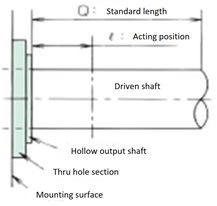 |
Note) For the hollow shaft Q: reference length, refer to Table 5 below.
Table 5. Sampling length: Q
Hypoid Motor
| Model number | Reduction ratio | Q |
|---|---|---|
| HMMT40H | 5 ~ 240 | 28 |
| HMMS40H | 5 ~ 240 | |
| HMMT60H | 5 ~ 240 | 36 |
| HMMS60H | 5 ~ 240 | |
| HMMT90H | 5 ~ 240 | |
| HMMS90H | 5 ~ 240 | |
| HMAT010-20H | 5 ~ 120 | |
| HMTA020-20H | 5 ~ 60 | |
| HMTA010-30H | 160 ~ 200 | |
| HMTA010-30H | 300 ~ 480 | 42 |
| HMTA020-30H | 80 ~ 200 | |
| HMTA040-30H | 5 ~ 50 | |
| HMTA010-35H | 600 ~ 1200 | 58 |
| HMTA020-35H | 300 ~ 480 | |
| HMTA040-35H | 60 ~ 200 | |
| HMTR075-35H | 5 ~ 50 | |
| HMTA020-45H | 600 ~ 1200 | 66 |
| HMTA040-45H | 300 ~ 480 | |
| HMTR075-45H | 60 ~ 200 | |
| HMTR151-45H | 5 ~ 80 | |
| HMTR221-45H | 5 ~ 60 | |
| HMTA040-55H | 600 ~ 1200 | 82 |
| HMTR075-55H | 300 ~ 480 | |
| HMTR151-55H | 100 ~ 200 | |
| HMTR221-55H | 80 ~ 120 | |
| HMTR370-55H | 5 ~ 60 | |
| HMTR550-55H | 5 ~ 40 |
Croise Motor
| Model number | Reduction ratio | Q |
|---|---|---|
| CSMA010-130H | 10 ~ 60 | 20 |
| CSMA020-130H | 10 ~ 60 | |
| HCMA010-16*H | 40 ~ 200 | 25 |
| HCMA020-16*H | 40 ~ 75 | |
| CSMA040-160H | 10 ~ 30 | |
| CSMA055-160H | 10 ~ 30 | |
| HCMA010-22*H | 240 ~ 300 | 30 |
| HCMA020-22*H | 90 ~ 200 | |
| HCMA040-22*H | 40 ~ 75 | |
| HCMA055-22*H | 40 ~ 50 | |
| CSMA040-220H | 40 ~ 60 | |
| CSMA055-220H | 40 ~ 60 | |
| CSMR075-220H | 10 ~ 30 | |
| HCMA020-28*H | 240 ~ 300 | 40 |
| HCMA040-28*H | 90 ~ 200 | |
| HCMA055-28*H | 60 ~ 150 | |
| HCMR075-28*H | 40 ~ 75 | |
| CSMR075-280H | 40 ~ 60 | |
| CSMR151-280H | 10 ~ 30 | |
| HCMA040-32*H | 240 ~ 300 | 50 |
| HCMA055-32*H | 180 ~ 200 | |
| HCMR075-32*H | 90 ~ 150 | |
| HCMR151-32*H | 40 ~ 50 | |
| CSMR151-32*H | 40 ~ 60 | |
| CSMR221-32*H | 10 ~ 40 | |
| HCMA055-40*H | 240 ~ 300 | 55 |
| HCMR075-40*H | 180 ~ 200 | |
| HCMR151-40*H | 60 ~ 120 | |
| HCMR221-40*H | 40 ~ 75 | |
| CSMR221-40*H | 50 ~ 60 | |
| CSMR370-40*H | 10 ~ 30 | |
| HCMR075-50*H | 240 ~ 300 | 70 |
| HCMR151-50*H | 150 ~ 300 | |
| HCMR221-50*H | 90 ~ 300 | |
| CSMR370-50*H | 40 ~ 60 |

