technical data Small size conveyor chain Handling
How to cut a chain
If you want to change the length of the chain you purchased, please follow the steps below to cut and connect the chain.
1. Grind the rivet part of the pin with a grinder
Use a grinder to grind down the ends of the two pins on outer link (the side with the attachment) until they are flush with the outer plate.
Be careful not to overheat the chain when grinding (Figs. 6 and 7).
In particular, for Lambda Chain, work slowly to avoid overheating the oil-impregnated bushings.
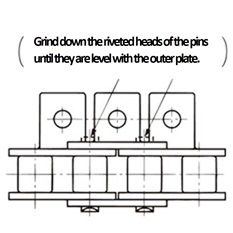
Figure 6. Chain with attachments
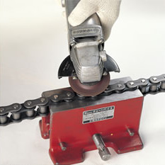
Figure 7. Shaving the end of the pin
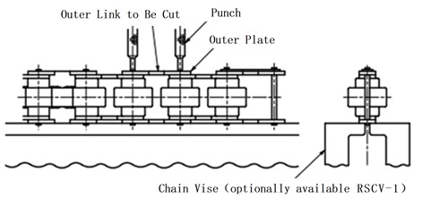
2. Place the chain in the chain vise or cradle
(1) S roller type (with A, SA, EP, GNK1 attachment)
With the attachment side facing up, pass the roller of the part to be disassembled through the groove of the chain vise and lightly tighten it with the jaws of the chain vise (Figures 8 and 9).
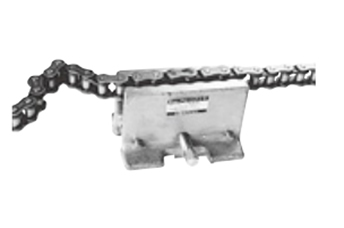
Figure 8. Setting the chain in the chain vise
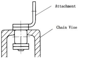
Figure 9. Cross section with chain set
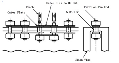
(2) S roller type (with K, SK attachments), R roller type (with K, SK attachments), plastic R roller type, Poly-steel chain (with attachments)
This type of chain is supported by a support like the one shown in Figure 11-1.
Another method, which is limited to steel S-roller types, is to place the pin to be removed at the end of the chain vise (Figure 11-2).
In either case, prepare suitable supports at the front and rear to stabilize the chain (Figure 10).
This method allows any attachment to be separated, but requires a larger force to remove the pin (item 3).
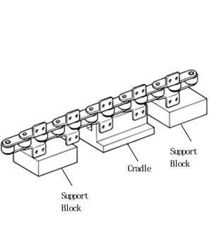
Figure 10. Cradle and support
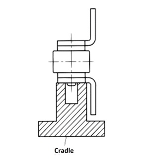
Figure 11-1. Cross section of the cradle
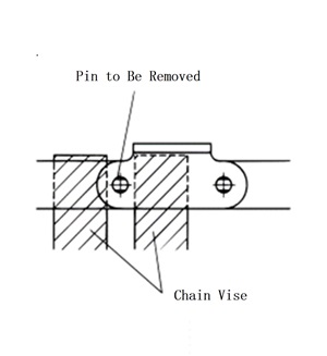
Figure 11-2. Using a chain vise
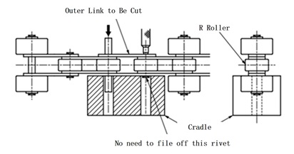
(3) R roller (A, SA, EP, with attachment)... Plastic Roller are not applicable.
Use a chain vise to clamp the plate on the side without the attachment, and support the R roller (Figure 13).
In this case, please also prepare suitable supports in front and behind (Figure 12).
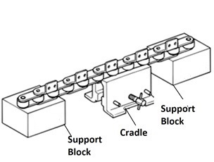
Figure 12. Chain vise and support stand
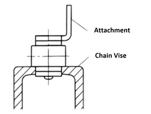
Figure 13. Cross section with chain set
3. Remove the pin
- (1) Place a primary punch (see the "Drive chain & Sprockets" catalog accessories section) that matches the size of the chain on the head of the pin that you ground down with a grinder, and strike the head of the primary punch with a hammer. At this time, strike alternately so that the pair of pins on outer link come out parallel. Continue striking until the pins are just about to come out of the outer plate (Figure 14).
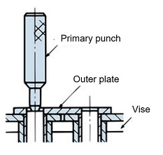
Figure 14. Hitting the pin with the primary punch
- (2) Use a secondary punch (see the "Drive chain & Sprocket" catalog accessories section) and a hammer to remove a pair of pins from the link. Check that the bushing in the area where the pin was removed has not come out of the inner plate or is not deformed. If it has come out or is deformed, do not use that part.
4. How to cut Poly-steel chain chain (a chain without attachments)
- (1) Support the outer plate of the chain on the support, press the head of the pin with the special punch (see photo), and lightly hit the head of the punch with a hammer (Figure 15).
- (2) At this time, please be careful not to apply too much force to the engineering plastic part, as this may cause damage.
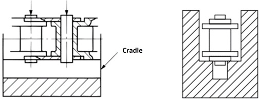
Figure 15. Cross section of Poly-steel chain set on the stand
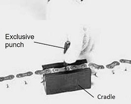
Figure 16. Disassembly of Poly-steel chain
⚠Safety Precautions
- 1. Be sure to use a grinder to remove the rivet portion of one end of the rivet-shaped pin. If you remove it as is, it will be more time-consuming and may damage the chain.
- 2. Do not reuse any removed parts.
5.How to cut Double Plus Free Flow Chains
- (1) Use a hand grinder to remove the rivet from the pin end of outer link to be cut.
- (2) Place Double Plus Free Flow Chains (if it has a snap cover, remove the snap cover for about three links at the cut end) in a chain vise (or equivalent) and use a primary punch or similar tool to drive in the pins until the upper outer plate comes off.
- (3) It can also be cut using a fork-shaped tool and a chain vise.

6. How to cut a chain with outboard roller
How to cut the main roller into an S shape
Poly-steel chain with outboard roller are listed below.
- (1) Decide which outer link to cut and mark it.
- (2) Place the chain in the chain vise (sold separately) as shown in the diagram above, and use a hand grinder or similar tool to remove the rivets on the pin ends (two on each side).
- (3) Use a pin (equivalent to a primary punch, sold separately) that is slightly thinner than the chain pin diameter to remove the two pins. Once the pins have been removed slightly, the two upper outboard roller will be able to be removed. (The above image shows outboard roller removed.)
- (4) Use a relatively small hammer to directly strike the pins until the ends of the pins reach the top surface of the outer plate. At this time, strike the pins alternately so that the two pins are removed equally.
It is important not to scratch the left and right outboard roller. - (5) Use the primary punch to remove the two pins until the upper outer plate is removed.
How to cut the main roller with an R shape

- (1) Decide which outer link to cut and mark it.
- (2) First, to remove the four outboard roller, grind off the rivets on the pin ends (four locations) with a hand grinder. At this time, grind down to the washer surface to remove the washer.
- (3) Remove the four outboard roller. (Method: Support outboard roller on the "receiving stand," and use a punch to knock out the end of the pin until the washer comes off. Repeat on the other side.)
- (4) Set the chain on the "receiving stand" as shown in the diagram above, and strike the primary punch with a hammer to remove the two pins. Please prepare a "receiving stand" as needed.
- (5) Proceed with the same procedure as steps (4) and (5) in "How to cut the main roller into an S shape."
- (6) If outboard roller are attached at intervals of more than two links, the location where the rivets need to be removed will change (see diagram below).
How to cut Poly-steel chain with outboard roller
- When outboard roller are installed in staggered type
- (1) Decide which outer link to cut and mark it.
- (2) As with "Cutting a Chain with an S-Shaped Main Roller," you can set the chain in a chain vise, but Inner link are made of engineering plastic, so they will be damaged. Therefore, this cutting method cannot be used.
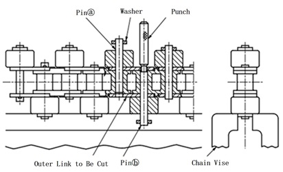
- (3) As shown in the figure above, lightly tighten the washer on the pin end with a chain vise. Since there are no rivets on the pin end of this chain, we can proceed with disassembly.
- (4) Using a pin (primary punch or equivalent, sold separately by our company) that is slightly thinner than the pin diameter of the chain, slowly hit the primary punch with a hammer, being careful not to apply a large impact, to remove the pin from the chain (see the diagram above). Stop the pin at the position where it has come out of the upper outer plate, as shown in the diagram above.
- (5) You can cut the wire by removing pins (a) and (b) in the same way. The above image shows the state after pin (a) has already been removed to the specified point and pin (b) has been removed.
- (6) Discard the cut outer link (see below).
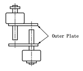
・When outboard roller are installed in parallel
- (1) Decide which outer link to cut and mark it.
- (2) As with "Cutting a Chain with an S-Shaped Main Roller," you can set the chain in a chain vise, but Inner link are made of engineering plastic, so they will be damaged. Therefore, this cutting method cannot be used.
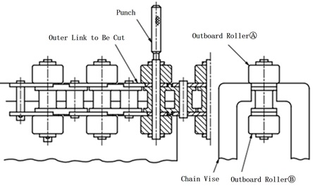
- (3) As shown in the diagram above, support the upper outboard roller (A) with a chain vise and lightly tighten the chain vise. At this time, bring the outer plate to be cut to the edge of the chain vise as shown in the diagram.
- (4) Place the primary punch on the pin end of outboard roller (A) and slowly hit the punch with a light hammer. outboard roller (A) will come off as shown in the diagram below.
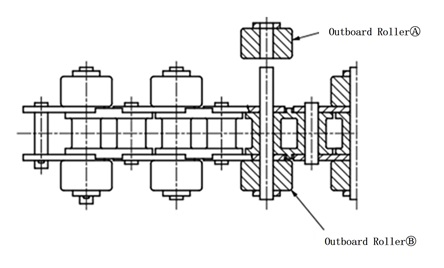
- (5) To remove outboard roller (B), turn the chain upside down and remove it in the same way as the roller (A).
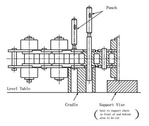
- (6) As shown in the diagram below, remove outboard roller (A) and (B) from the chain and place it on the "receiving stand." Lightly hit the primary punch with a hammer to remove the two pins. Continue removing the pins until the upper outer link is removed. (Please prepare a receiving stand as needed.)
7. How to cut a chain with top rollers
- (1) Place a recognition mark on outer link to be cut.
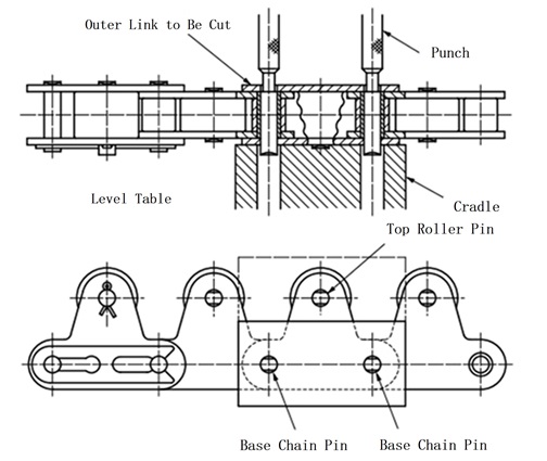
- (2) Use a hand grinder or similar tool to remove the rivets on the ends of the main pin and top roller pin (three places on one side of the chain).
- (3) Place the chain on the "receiving stand" as shown in the figure, with the grinder side facing up. Please prepare a "receiving stand" as needed.
When removing three pins, including the top roller pin, at the same time, make a "receiving base" by combining the parts shown by the imaginary lines. - (4) Use a hammer to hit the primary punch (or equivalent) until the two (three) pins are released from the outer plate (as shown in the figure) to remove the pins.
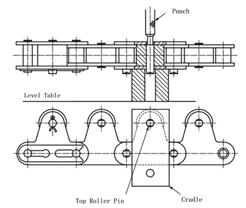
- (5) Next, to remove the top roller pin, change the position of the "receiving base" as shown in the diagram below. (If outer link does not have a top roller, this step is not necessary.)
- (6) Remove the top roller pin in the same way as in (4).
How to splice a chain
1. Connected with connecting links
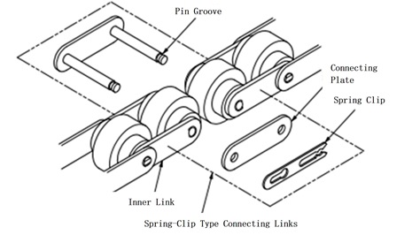
- 1) Insert the connecting link into the connecting part of Inner link, attach connecting link plate, and then secure it with spring clip or cotter pin.
- 2) connecting link plate and pin are slip fit, so they can be inserted by hand.
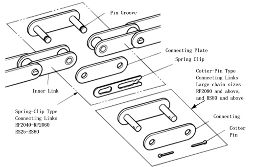
Figure 17. Connection of chain with attachment
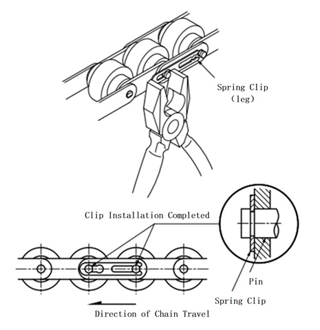
2. Installing spring clip
Be sure to install the connecting link spring clip securely. Forgetting to install spring clip or installing it improperly can cause an unexpected accident.
- 1) spring clip are used on connecting links of RF2060, RS60 and smaller chains. When connecting, insert connecting link plate into the pin, then insert spring clip securely into the groove in the pin of the connecting link (Figures 18 and 19).
- 2) Be careful not to spread the legs of spring clip too far, as it may not be inserted correctly and may fall off, causing an unexpected accident (Figs. 19 and 20).
Figure 18. Insert spring clip into the pin groove
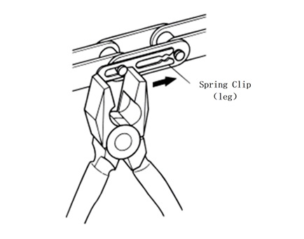
Figure 19. Secure spring clip with pliers
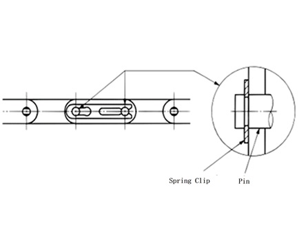
Figure 20. spring clip installation completed
- 3) spring clip installation direction relative to the chain's direction of travel is generally as shown in the diagram below (Figure 21).
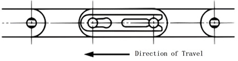
Figure 21. spring clip installation direction
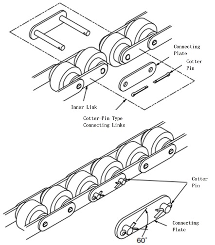
3. Installing the cotter pin
Be sure to install the cotter pin of the connecting link securely. Forgetting to install the cotter pin or installing it improperly can cause an unexpected accident.
- 1) The split pin legs should be spaced at an angle of approximately 60° (Figure 22). Do not reuse split pins or use commercially available split pins.
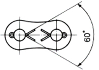
Figure 22. Split pin opening
- 2) How to open the split pin
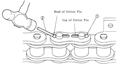
Figure 23.
- (1) Insert the cotter pin into the cotter pin hole.
- (2) Lightly tap the head of the cotter pin with a pin that is slightly thicker than the cotter pin diameter to open the legs of the cotter pin slightly.
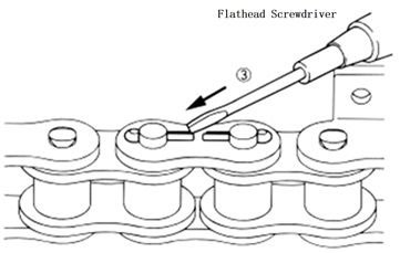
Figure 24.
- (3) Insert the tip of a flat-head screwdriver into the space where the legs of the cotter pin are slightly open.
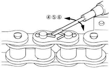
Figure 25.
⚠Caution
Be careful when working so that the tip of the screwdriver does not slip and hit your hand or other parts of your body.
- (4) Insert the tip of the screwdriver diagonally into the split pin and move the screwdriver left and right to open the legs of the split pin.
- (5) At this time, press down on the head of the cotter pin to prevent it from slipping out of the cotter pin hole. This will ensure a tight fit.
- (6) The opening angle of the split pin legs is as described above.
4. Double Plus Free Flow Chains
1) Connect with spring clip (sizes below RF2060)
- (1) Pass the two pins of the connecting link through the bushings of Inner link and then through the holes in connecting link plate.
- (2) Place spring clip securely into the pin groove.
2) Connect with a split pin (RF2080)
- (1) Pass the two pins of the connecting link through the bushings of Inner link and then through the holes in connecting link plate.
- (2) Pass the split pin through the pin hole and open the legs to about 60 degrees.
5. Chain with outboard roller
Connect the chains using connecting links.
1) staggered type outboard roller joint
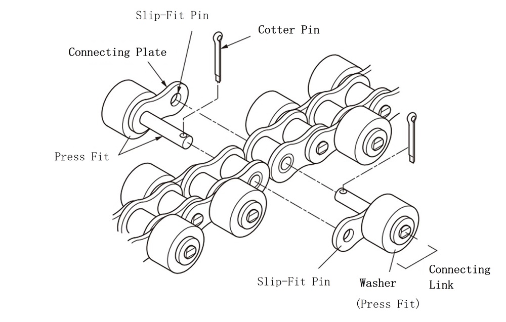
- (1) Insert the two pins of the connecting link into the holes in each Inner link, and then pass them through slip fit connecting link plate.
- (2) Insert a split pin into each pin and open the legs of the split pin to about 60°.
2) Joining with parallel outboard roller
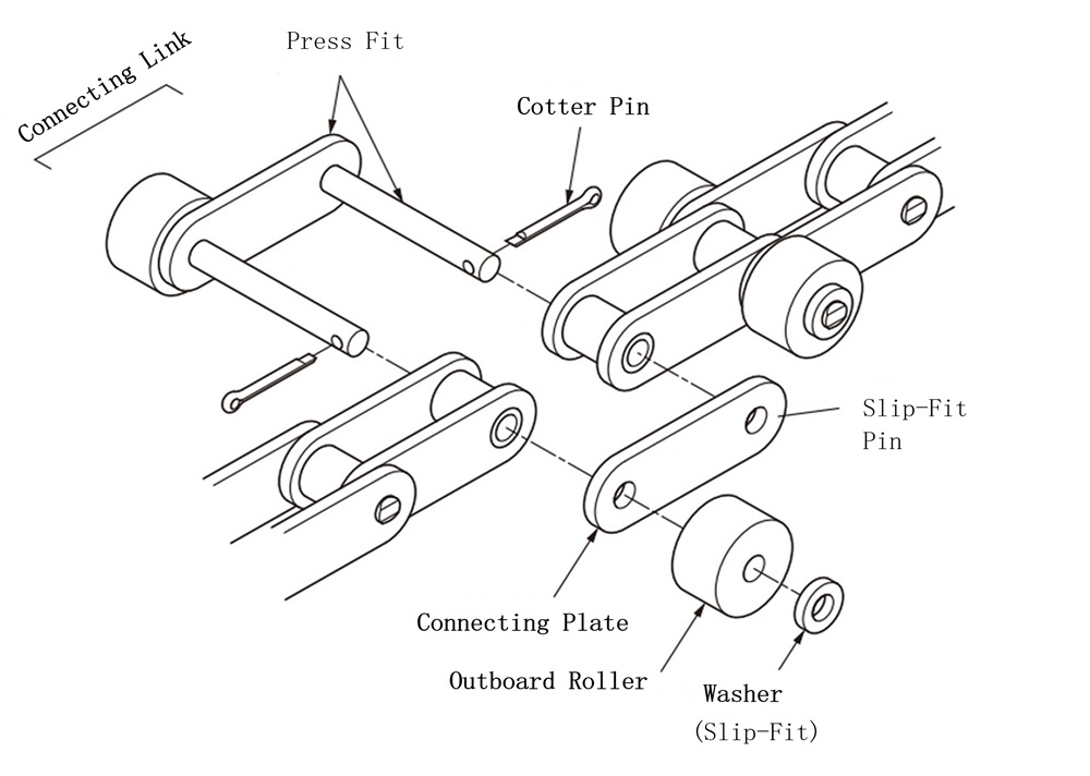
- (1) Pass the two pins of the connecting link through the holes in Inner link and then through slip fit connecting link plate.
- (2) If the pin has outboard roller on both ends as shown in the illustration, pass outboard roller and washers through the pin and attach two cotter pins. The opening angle of the cotter pin is approximately 60°.
6. Chain with top rollers
- (1) Connection is made using connecting links.
- (2) Pass the two pins of the connecting link through the bushings of Inner link and then through the holes in connecting link plate. (connecting link plate is slip fit.)
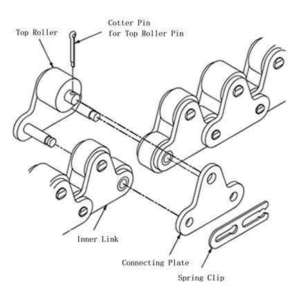
spring clip type connecting link
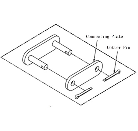
cotter type connecting link
- (3) Securely attach the cotter pin or spring clip to the pin. The legs of the cotter pin should open at approximately 60 degrees. How to attach spring clip is explained in detail in the section on Double Plus Free Flow Chains.
Connecting links for top roller chains
- 1. There are two types of connecting links, so please be careful when ordering connecting links only.
- 2. The outer diameter of the top rollers differs between the top rollers with top rollers every link and those with top rollers every two links below. Please also refer to the dimension drawings. (Double pitch top roller diameters are the same.)
- 3. If the connecting link has an attachment other than a top roller, please specify it in a separate drawing, etc. (Connecting link symbol: JL)
With Plastic top rollers per link
Model number display example
| RS40-1LTRPS | - | JL |
| | Main chain |
| Connecting Link |
|
With Plastic top rollers every two links
Model number display example
| RS40-2LTRP | - | JL |
| | Main chain |
| Connecting Link |
|

