technical data Selecting Small size conveyor chain
Please refer to the following dimensions when manufacturing and installing Double Plus Free Flow Chains conveyor design data.
1. Position of both ends of the conveyor and the sprocket
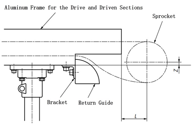
| Size & Roller Type | Rail Number | Z | L |
|---|---|---|---|
| RF2030VRP | RF2030VRP-R2 RF2030VRP-R2S |
21.3 | 40 |
| RF2040VRP | RF2040VRP-R2 RF2040VRP-R2S |
14.7 | 50 |
| RF2050VRP | RF2050VRP-R2 RF2050VRP-R2S |
16.1 | 60 |
| RF2050VRP-R2HS | 76.2 | 60 | |
| RF2060VRP | RF2060VRP-R2 RF2060VRP-R2S |
14.9 | 70 |
| RF2080VRP | RF2080VRP-R2S | 24 | 100 |
2. Aluminum frame processing dimensions
The RF2050VRP-R2HS rail in Table 17 does not have an aluminum frame for the drive and driven parts.
Please refer to the dimensions in Table 17 when performing additional machining on the intermediate frame.
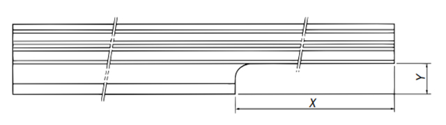
| Size & Roller Type | RF2050VRP |
|---|---|
| Rail Number | RF2050VRP-R2HS |
| X (drive side) | 340 |
| X (driven side) | 120 |
| Y | 30 |
3. Mounting bolts and conveyor height
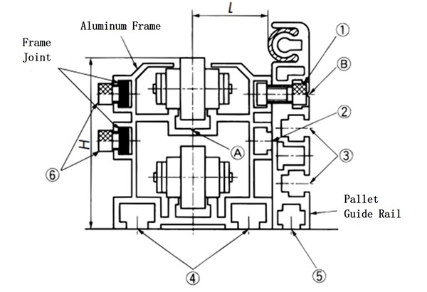
| frame | (1) | (2) | (3) | (4) | (5) | (6) | H | L |
|---|---|---|---|---|---|---|---|---|
| RF2030VRP-R2 RF2030VRP-R2S |
M6×10 | M6 | M5 | M6 | M5 | M6×8 | 61.5 | 14.5 |
| RF2040VRP-R2 RF2040VRP-R2S |
M6×12 | M6 | M6 | M8 | M6 | M6×8 | 68 | 28.5 |
| RF2050VRP-R2 RF2050VRP-R2S |
M8×20 | M8 | M8 | M10 | M8 | M8×10 | 82.5 | 36 |
| ※RF2050VRP-R2HS | M8×20 | M8 | M8 | M10 | M8 | M8×10 | 142.5 | 37 |
| RF2060VRP-R2 RF2060VRP-R2S |
M8×20 | M8 | M8 | M10 | M8 | M8×10 | 95 | 44.5 |
| RF2080VRP-R2S | M8×25 | M8 | M8 | M10 | M8 | M8×12 | 130 | 47 |
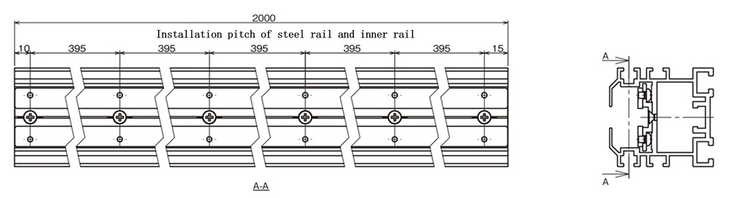
- 1) Alignment between aluminum frames
Align the position with the V-groove indicated by the arrow (A) in the diagram above as a reference, and secure it to the base with the bolt in Table 18 (4). - 2) Aluminum frame connection
After alignment, it can be secured with the frame joint.
*The frame joint is not for aligning aluminum frames. - 3) Pallet guide channel installation
Drill a hole of the required size in the V-groove position indicated by the arrow (B) in the illustration, and attach it with the hexagon bolt in Table 18 (1). - 4) *In the table above, there is a 60mm difference in height between the aluminum frame and the pallet guide channel.
Please use a height adjustment collar under the pallet guide channel.
4. Conveyor leg pitch
Determine based on the weight of the load being transported and the moment of inertia shown in Table 19. However, regardless of the moment of inertia, design the frame connections so that they are supported by the legs.
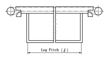
How to calculate leg pitch (ℓ)
- I = Moment of inertia (cm 4) (see Table 19)
- W = Load mass (kg/m)
- δ = deflection (2 mm)
- E = 7.0 × 10 3 (kg/mm 2)
Note: The load mass (W) is set to (0.6W) to take into account the load imbalance, as two chains are used in parallel.
| classification | Frame model number | Moment of inertia (I) cm 4 |
|---|---|---|
| Aluminum frame | RF2030VRP-R2 | 17.127 |
| RF2040VRP-R2 | 40.185 | |
| RF2050VRP-R2 | 84.039 | |
| RF2060VRP-R2 | 135.137 | |
| With steel rails Aluminum frame |
RF2030VRP-R2S | 17.821 |
| RF2040VRP-R2S | 44.312 | |
| RF2050VRP-R2S | 95.623 | |
| RF2050VRP-R2HS | 442.093 | |
| RF2060VRP-R2S | 171.761 | |
| RF2080VRP-R2S | 360.726 |
*The second moment of area (I) of the drive and driven frame is the same as above.
5. Aluminum frame with steel rails
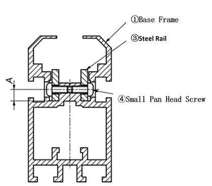
1) Cross-sectional structure
RF2030VRP
RF2040VRP~RF2080VRP
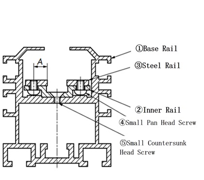
| Frame model number | Steel rail (product number 3) | Steel rail mounting screws (item no. 4) Cross-recessed pan head screw |
Inner rail mounting screws (item no. 5) Cross-recessed flat head machine screw |
||
|---|---|---|---|---|---|
| For intermediate use | For driving and driven use | size (Plate thickness x width) |
A dimension | ||
| RF2030VRP-R2S | RF2030VRP-R1SK, -R1SJ | 3×13 | 4.75 | M3×7 | - |
| RF2040VRP-R2S | RF2040VRP-R1SK, -R1SJ | 3×13 | 8.4 | M4×5 | M4×6 |
| RF2050VRP-R2S | RF2050VRP-R1SK, -R1SJ | 3×13 | 8.4 | M4×6 | M4×6 |
| RF2050VRP-R2HS | - | 3×13 | 8.4 | M4×6 | M4×6 |
| RF2060VRP-R2S | RF2060VRP-R1SK, -R1SJ | 3×13 | 8.4 | M4×6 | M4×6 |
| RF2080VRP-R2S | RF2080VRP-R1SK, -R1SJ | 6×16 | 10.5 | M5×8 | M6×10 |
2) Intermediate frame assembly diagram
3) Assembly diagram of the drive and driven frame
- ・RF2050VRP-R2HS does not have a frame for the drive and driven parts.
- ・There is a notch on the bottom right edge of the image above. (Example of RF2030VRP-R1K)
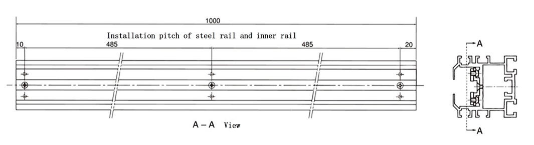
4) Important points to note when handling aluminum frames with steel rails
- 1. When cutting an aluminum frame with steel rails
- (1) Cut the center of the frame or the area other than the screw part.
- (2) Remove any burrs that have occurred on the cut surface.
- (3) Screw the steel rail and inner rail, and the inner rail and main frame together 15 to 30 mm from the cut surface.
- (4) All machining is done on individual parts, and any burrs or chips that may have been generated during machining are completely removed before reassembly. Also, be sure to avoid any misalignment at the 45° cut.
- 2. Frame connection
After connecting the frames, if there are any unevenness (vertical or horizontal) on the mating surfaces of the steel rails, chamfer them slightly to prevent the chain rollers from getting caught.

