technical data Clutch Handling
LD Series Handle with care
- 1. We recommend that the inner diameter tolerance of pulleys, etc. attached to outer race be H6 or H7.
- 2. The cam and roller structure means that the roller type bearing is built in. When inserting or removing inner race, please do so gently to prevent the roller from falling off.
- 3. When mounting the bearing onto the shaft, apply pressure to the end face inner race and gently insert it in. At this time, be careful not to let it fall out of outer race.
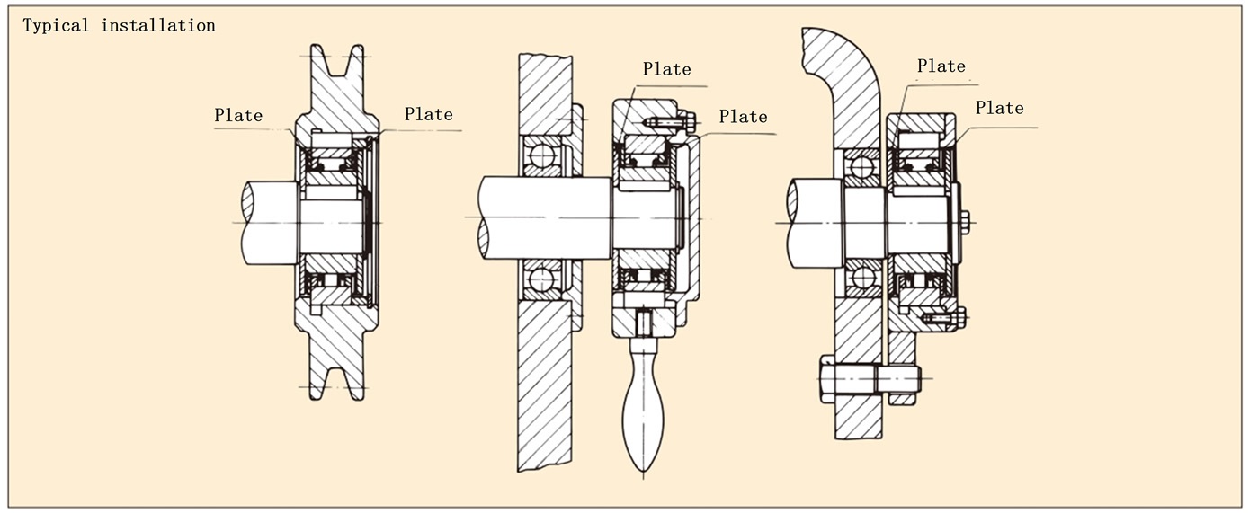
- 4. To prevent outer race from moving left and right, please make and attach a plate (dimensions here). If the plate is not attached, outer race of the Cam Clutch will come off to the left and right.
- 5. Apply grease between the plate and the thrust metal (see installation example).
- 6. If a thrust load is applied to the Cam Clutch, provide a separate device to bear the thrust load.
- 7. If a radial load exceeding the allowable value is applied during idling, install bearings on both sides.
- 8. The outer diameter of the Cam Clutch and the bearing with the same outer diameter are listed in the dimension table on the product page for the bearing to be installed in the Cam Clutch.
- 9. Use JIS B1301-1959 (old JIS) parallel key type 2. Please note that outer race key dimensions do not conform to the relationship between shaft diameter and key specified in JIS.
- 10. For information on lubrication and maintenance, please see here.
×
(You can move it by dragging it)
Recommended plate dimensions
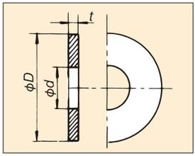
| Size | t | Φd | ΦD |
|---|---|---|---|
| LD04 | 2 | 10 | 40 |
| LD05 | 2 | 14 | 45 |
| LD06 | 3 | 20 | 52 |
| LD07 | 3 | 25 | 62 |
| LD08 | 3 | 30 | 70 |