technical data Drive chain Glossary
1. JIS minimum tensile strength (tensile breaking strength)
The minimum tensile strength specified by JIS. If a JIS product breaks under a load lower than this, it fails the JIS standard. multiple strand roller chain must have a tensile strength that is multiple of No. of strands of single strand. (JIS B 1801: 2014)
It is also ISO compliant (ISO 606: 2004).
2. Minimum tensile strength
This is the minimum value determined by statistical processing of our actual results. When any roller chain undergoes a tensile test, if it breaks at a load lower than this value, it will fail. This value varies depending on the manufacturer.
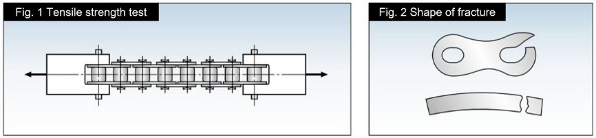
Test Method
As shown in Figure 1, both ends of a roller chain with an effective length of 5 or more links are fixed with a jig and pulled until it breaks (JIS B 1801: 2014).
The type of failure is disassembly of the roller chain or destruction of parts (Figure 2).
3. Maximum allowable load
Maximum allowable load of roller chains (excluding stainless steel and engineering plastic*) is their fatigue limit. If the load is below this value, the roller chain will not break due to fatigue even if it is repeatedly loaded.
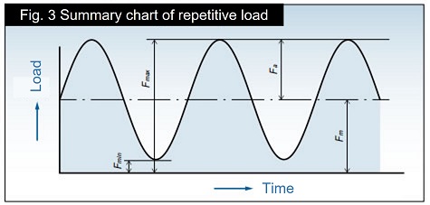
According to JIS B 1811:2018, when a roller chain with 5 or more effective links is subjected to the repeated load shown in Figure 3 in a straight state, the minimum tension is set to 0 when the probability of failure after10 7 cycles (10 million cycles) is calculated as 0.135%. This is the test tension (Fd) corrected to 0.
*For stainless steel and engineering plastic products, the surface pressure between the pin and bushing is specified based on wear performance, and Maximum allowable load is determined.
Offset links can be weaker than the main body of the roller chain.
Fd = Fu(Fmax - Fmin) Fu - Fmin
F u: JIS minimum tensile strength
4. kW ratings table
kW ratings table for RS roller chain, RS-HT chain Super chain, Low-noise chain show the power transmission kW that can withstand up to 15,000 hours when a 100-link roller chain is used for two-axis power transmission under the conditions below (1 to 5).
- 1) Operate in an indoor environment between -10℃ and 60℃, and be free from dust.
- 2) There is no adverse effect from the environment such as corrosive gases or high humidity.
- 3) The two transmitting shafts are horizontal and properly positioned and installed.
- 4) Transmission with minimal load fluctuations.
- 5) For RS roller chain, Super chain, RS-HT chain, and Low-noise chain, use the lubricant recommended in kW ratings table that is suitable for the operating conditions.
5. Moment of Inertia
Moment of inertia is used to express the inertia in rotational motion, that is, the degree of "difficulty in turning" or "ease of turning."
This corresponds to the mass (weight) of an object moving in a straight line.
The moment of inertia in the SI unit system is given by I = M K2 (kg·m 2 M: mass of the rotating body K: radius of rotation).
The moment of inertia I in the gravitational unit system is given by I = G・ K2 G (kgf・m・S 2 G: weight of the rotating body G: gravitational acceleration).
Generally, GD 2 = 4 G I (D: diameter of the rotating body) has been used instead of the moment of inertia.
6. Roller chain overall length tolerance
JIS B 1801: 2014 specifies the length test method and length tolerance.
The length tolerance when applying the measurement load specified by JIS for each size (500N for RS80-1) is set to 0 to + 0.15% of the standard length.
The standard length is calculated by multiplying the standard chain pitch (P) by the number of links. (Applies to products with JIS nominal numbers.)
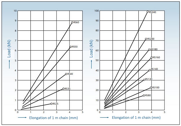
7. Elastic elongation of chain due to load
The elastic elongation curve when a load is applied to a chain is shown in the diagram below. The values shown here are standard guideline values for single strand RS roller chain.
Do not apply a load to the roller chain that exceeds Maximum allowable load.