technical data Drive chain Roller Chain Handling
4. Roller chain layout and installation
4.1 Speed ratio and winding angle
A speed ratio of up to 7:1 is appropriate for roller chain transmission, but at very low speeds it is possible to go up to around 10:1. The winding angle between the small sprocket and the chain must be 120° or more.
However, if it is for hanging use, it must be at least 90°.
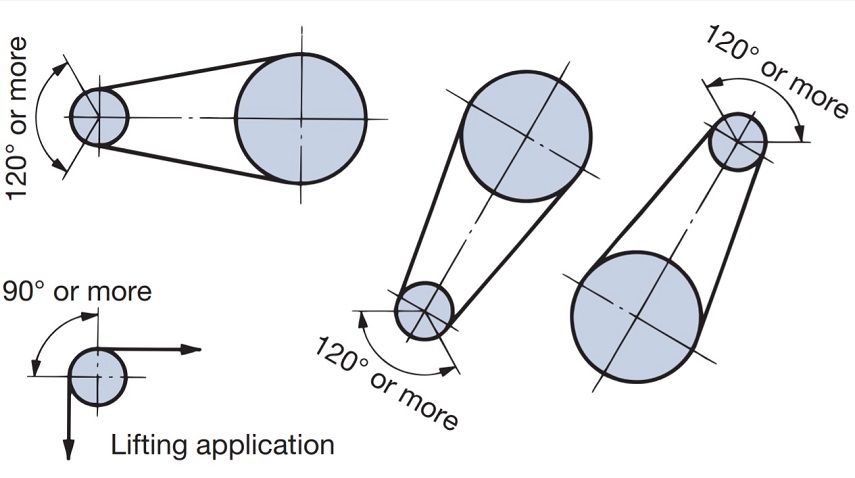
Figure 13. Wrapping angle
4.2 Center distance
The shortest distance is the distance where the teeth of the two sprockets do not come into contact. The most desirable center distance between the two shafts is about 30 to 50 times the pitch of the roller chain used.
However, when a fluctuating load is applied, it is appropriate to keep it below 20 times.
4.3 Slack
1. Roller chain transmissions do not require the initial tension that is required for V-belts or flat belt transmissions.
Generally, roller chains should be used with an appropriate amount of slack. If the roller chain is too tight, an oil film will not form between the pins and bushings, which will accelerate damage to the roller chain and bearings.
Also, if the roller chain is too slack, it will vibrate and get caught in the sprocket, damaging both the roller chain and the sprocket.

Figure 14. Example of sagging
2. In roller chain transmission, the lower side should be the slack side whenever possible.
The appropriate amount of slack is the amount that, when you manually move the center of the slack side in a perpendicular direction, the distance SS' is about 4% of the span AB.
(For example, if the span length is 800 mm, the amount of slack will be 800 mm x 0.04 = 32 mm.)
In the following cases, set it to around 2%.
- ・Vertical transmission or similar arrangement
- ・When the distance between axes is 1m or more
- ・When starting frequently with heavy load
- ・When the flow suddenly reverses
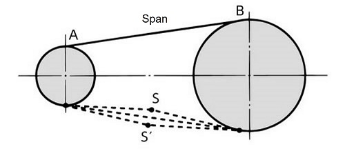
Figure 15. Amount of slack
3. During the first few dozen hours of use, roller chains will stretch by about 0.05% as the contact surfaces of each part break in.
Therefore, it may be necessary to adjust the amount of slack in the roller chain.
If you have a tensioning device, use it. If you don't have a tensioning device, adjust the slack by moving the bearings. As the chain breaks in, the stretch will decrease.
4.4 Parallelism and levelness of shafts
The accuracy of sprocket installation affects the smooth movement of the roller chain and determines the lifespan of the roller chain.
1. Use a spirit level to make sure the shaft is level.
The accuracy is adjusted to ±1300.
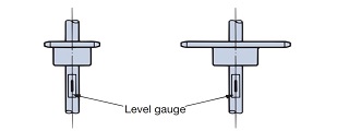
Figure 16. Shaft horizontality
2. Use a scale to determine the parallelism of the shaft.
Adjust the parallelism of the shaft so that it is ± 1300 ≧ A - BL.
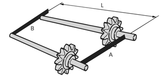
Figure 17. Parallelism of shafts
3. Using a tool that can measure the parallelism of flat surfaces, such as a straight edge or Easy Laser, adjust the pair of sprockets so that they are on the same plane. Depending on the center distance of the sprockets, install them so that the following values are obtained.
- Up to 1m: ±1mm
- 1 to 10m: ± Distance between shafts (mm)1,000
- 10m or more: ±10mm
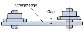
Figure 18. Sprocket facing
The sprocket is secured to the shaft with Power-Lock, Lock Sprocket, or key.
Adjustment parts such as collars and set bolts may also be required.
4.5 Placement
1. General layout
The ideal arrangement for roller chain transmission is one in which the line connecting the centers of both sprockets is nearly horizontal. If the arrangement is nearly vertical, the roller chain will easily come off the sprocket even if it stretches a little, so use an idler or tensioner. The inclination angle should be within 60° as much as possible.
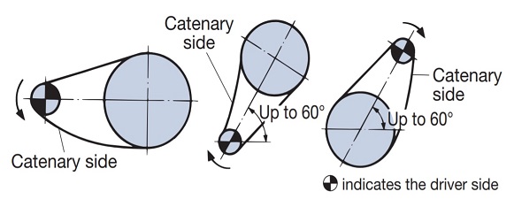
Figure 19. Typical layout
2. Placement considerations
・If the upper side is the sagging side
If the center distance is short, move the bearing to increase the center distance of the sprockets and adjust the tension slightly.

Figure 20: Example of adjustment when the center distance is short
If the center distance is long, an intermediate idler is placed on the inside of the slack to support the roller chain.
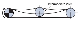
Figure 21: Example of adjustment when the center distance is long
- When the chain speed is high and a fluctuating load is applied
The natural frequency of the roller chain and the impact cycle of the driven machine, or the chordal action of the roller chain (up and down movement of the roller chain due to polygonal motion), may synchronize, causing the roller chain to vibrate.
In such cases, vibrations can be suppressed by using vibration-preventing devices such as guide stoppers (made of NBR or ultra-high molecular weight polyethylene).
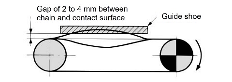
Figure 22. Example of vibration prevention
・When the center line is vertical
Install a tensioner that automatically adjusts for excess slack to ensure proper engagement with the sprocket, especially on lower drive shafts.
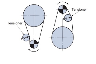
Figure 23. Example of adjustment for vertical transmission
4.6 Installation of curved chains
1. Setting up guides
Curved chains have more freedom of movement than RS roller chain, so guides are provided on the chain to ensure it meshes straight with the sprockets.
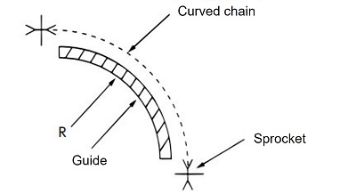
Figure 24. Guide diagram
2. Minimum side bending radius (r)
Install the guide so that the R dimension of the guide is equal to or greater than the minimum lateral bending radius in the table below.
| Product name | Minimum lateral bending radius (r) |
|---|---|
| RS40-CU-1 | 350 |
| RS50-CU-1 | 400 |
| RS60-CU-1 | 500 |
| RS80-CU-1 | 600 |
| RS40-LMCCU-1 | 400 |
| RS50-LMCCU-1 | 500 |
| RS60-LMCCU-1 | 600 |
| Product name | Minimum lateral bending radius (r) |
|---|---|
| RS40-CUSS-1 | 400 |
| RS50-CUSS-1 | 500 |
| RS60-CUSS-1 | 600 |
| RS80-CUSS-1 | 800 |

