technical data Pin gear drive unit
Selection Procedure
Tentative selection of pitch circle diameter for Pin gear drive unit
| During rotational motion: | Preliminary select the pitch circle diameter of the pin wheel based on the size of the rotating device. Preliminary select the pitch circle diameter of the pin gear based on the reduction ratio. |
| During linear motion: | Please provisionally select the pitch circle diameter of the pin gear based on the equipment layout. |
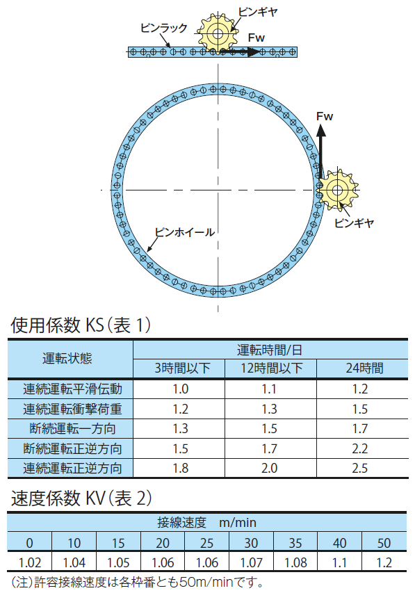
Calculation of applied tangential load Fw
Calculate the applied tangential load Fw acting on the pin wheel or pin rack from the load conditions.
Calculation of corrected tangential load Ft
Obtain Service factor KS (Table 1) from the operating conditions and the speed coefficient KV (Table 2) from the tangential speed, and multiply these by the applied tangential load FW to obtain the corrected tangential load FT.
Pin gear drive unit frame number selection
Select Pin gear drive unit frame number that satisfies the following conditions based on the allowable tangential load FP and corrected tangential load FT for each frame number of the pin rack or pin wheel.
Model number selection
| Pinwheel: | Select the number of rollers for the pinwheel with the closest pitch circle diameter to the selected frame number and the pitch circle diameter of the provisionally selected pinwheel. |
| Pin Rack: | Calculate the number of rack rollers from the selected frame number and travel distance (or travel distance). |
| Pin Gear: | From the selected frame number and the provisionally selected pitch circle diameter of the pin gear, select the number of teeth of the pin gear with the closest pitch circle diameter to determine the model number. |
| *There is a limit to the number of gear teeth that can be used. If the number of teeth is insufficient, please increase the number of teeth and reselect. | |
[Click to enlarge]
Lubrication
Before operation, be sure to apply extreme pressure grease to the outer periphery of all rollers. The inner surface of the rollers of the pin wheel or pin rack has been pre-applied with lubricating grease.
Please contact us if you plan to use the product in an environment where lubricating grease cannot be used, such as underwater, or in a high-temperature environment of 130°C or higher.
Special backlash specifications (Different from the standard allowable tangential load)
● Large backlash specification
Increasing the backlash allows for easy installation.
● Low backlash specification
Backlash can be reduced. (2/3 of standard backlash, compatible frame numbers: PDU020 to PDU120)
Installation Method
Flat Wheel
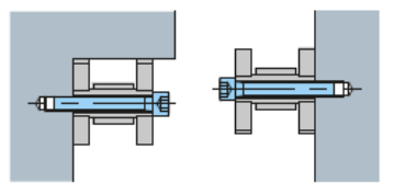
A hollow pin is used, so the hole can be used to fasten the side to the mating device with a bolt. When mounting, a stopper or guide can be provided on one side to determine position.
angle

The straight angle rack can be fixed to the mating device using the bolt fastening holes on the legs.
Mounting bolt position
The bolts must be installed at both ends of the segments and in equal intervals between them, with at least the minimum number of bolts installed (see below).
■ Minimum number of mounting bolts per segment (for horizontal mounting)
| Specification | Frame No. | Mounting bolt size | minimum Number of attachments |
|---|---|---|---|
| Steel type | PDU020 | M4 | 8 |
| PDU022 | M4 | 13 | |
| PDU030 | M6 | 10 | |
| PDU035 | M8 | 8 | |
| PDU040 | M10 | 7 | |
| PDU050 | M12 | 6 | |
| PDU055 | M12 | 9 | |
| PDU070 | M16 | 6 | |
| PDU080 | M16 | 7 | |
| PDU090 | M20 | 6 | |
| PDU120 | M30 | 4 | |
| PDU150 | M36 | 6 | |
| PDU180 | M42 | 6 | |
| PDU240 | M48 | 5 | |
| stainless type | PDU020 | M4 | 8 |
| PDU022 | M4 | 13 | |
| PDU030 | M6 | 10 | |
| PDU035 | M8 | 8 | |
| PDU040 | M10 | 7 | |
| PDU050 | M12 | 6 | |
| PDU055 | M12 | 9 | |
| PDU070 | M16 | 6 | |
| PDU080 | M16 | 7 | |
| PDU090 | M20 | 6 |
| (example) | Bolt Mounting: | PDU050-GPF064P 4-split |
| Installation Position: | See the diagram below (the black circle indicates the installation position) | |
| PDU050 minimum number of mounting bolts: 6 (M12) Install six or more bolts per segment, spaced as evenly as possible. *If you have any questions regarding installation, please contact us. |
||
[Click to enlarge]
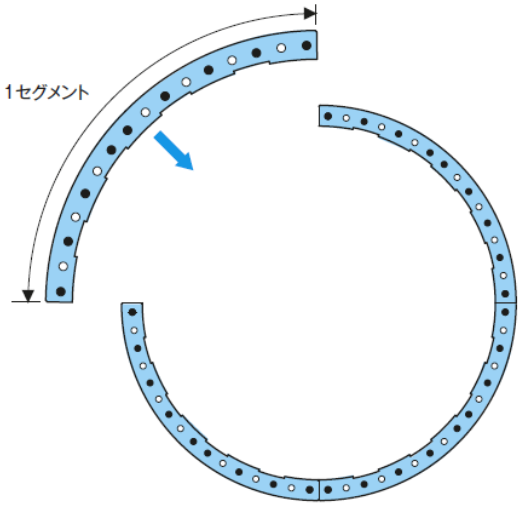
Pinwheel/pin rack division
Please refer to the following for details on dividing the pin wheels and pin racks, and be sure to check the delivery diagram when placing your order.
| Example 1. | Pinwheel example: | Example 2. | Pin rack example: | ||||
| In the case of PDU30-GW-190P, it is divided into 8 parts. | For PDU30-FR-200P, number of standard length rollers: 26P, minimum number of rollers: 10P | ||||||
| 23/190P x 2 | ) | It will be a combination of. | 26P x 7 | ) | It will be a combination of. | ||
| 24/190P x 6 | 18P x 1 | ||||||
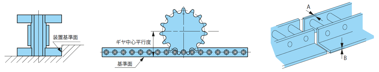
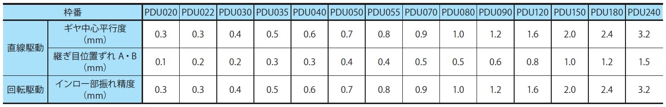
Installation Accuracy
| Pinwheel: | The convex surface of the pinwheel frame is machined to be concentric with the roller mounting hole, so it can be fitted into the spigot part of the device and used as a centering reference surface. The precision of the inlay part of the device must be finished within the "Inlay part runout precision" in the table below. |
| Pin Rack: | Please ensure that the parallelism between the pin rack equipment side mounting reference surface and the pin gear center is equal to or less than the "Gear center parallelism" value in the table below. Install the pin racks so that the mutual positional deviations A and B at the joints between them are less than the values in the table below. |
[Click to enlarge]
[Click to enlarge]
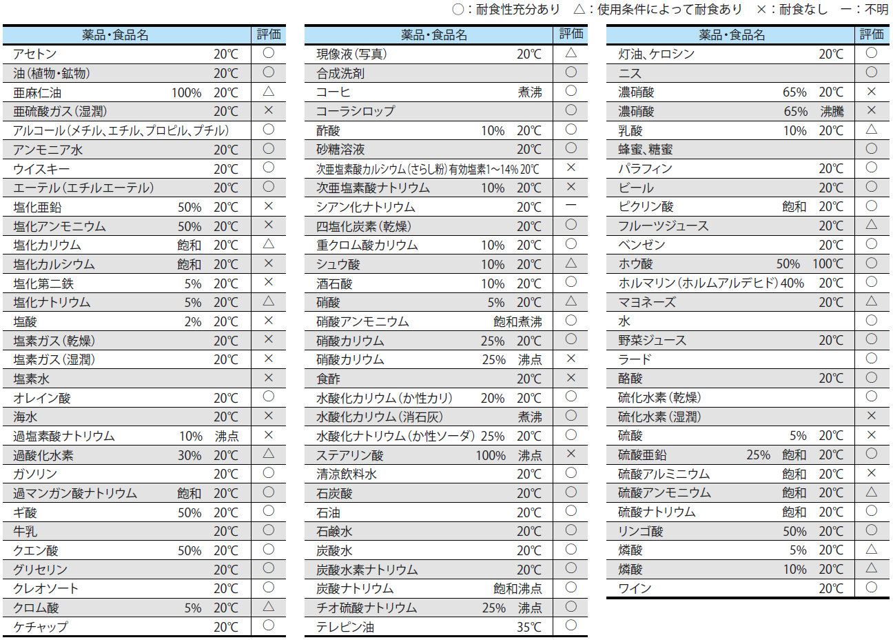
Reference material on corrosion resistance of stainless steel types
Corrosion resistance varies considerably depending on the conditions of use, so the table below does not represent the degree of guarantee. Please refer to the table below and check the corrosion resistance in advance using test samples under the actual conditions of use.
[Click to enlarge]

