Linipower Jack Simple Selection Tool
Target varieties
Linipower Jack JWB (Ball screw type)
Linipower Jack Jack JWH (High lead ball screw type)
Linipower Jack JWM (Trapezoidal Screw type)
Use of Content
- When using TSUBAKI Power Transmission Products Information Site Linipower Jack Simple Selection Tool (hereinafter referred to as "this tool"), please be sure to read the following usage precautions and disclaimers, and use this tool only if you agree to all of the contents.
- If you do not agree, please refrain from using this tool.
Precautions for use and disclaimers
Sizing Linipower Jack
- ・We will select the model that best suits your specifications.
- ・After entering the selection criteria, etc., click the decision button at the bottom of the screen.
- ・This is sizing software for one jack.
When selecting multiple units, please refer to [STEP 1 Selecting Linipower Jack 2. Calculating the load W per jack].
Enter the selection criteria
・Please use “.” for the decimal point and not “,” as the calculation error will occur.
Please enter your selection criteria.
| Lifting load (maximum) | W0 = | [kN] | [kgf] |
Table 1 Service factor sf
Note: The above Service factor table is a general guideline. Please determine the coefficient taking into consideration the usage conditions. |
||||||||||||
| Lifting load (minimum) | W1 = | [kN] | [kgf] | |||||||||||||
| Service factor | Sf = | |||||||||||||||
| Buckling strength confirmation load | W2 = | [kN] | [kgf] | |||||||||||||
| Desired lift speed | V' = | [m/min] | [mm/s] | |||||||||||||
| Stroke | ST0 = | [mm] | ||||||||||||||
| Actual stroke | ST = | [mm] | ||||||||||||||
| Operating frequency | [Round trip/Hr]×[Hr/day]×[day/year] | |||||||||||||||
Linipower Jack specifications decided
Please select the specifications of Linipower Jack.
[Display model number reference example]
| JW | M | 050 | U | S | H | 10 | U |
| | Series Name Linipower jack |
| | | | | | | | | | | | | | |
| Basic capacity 002: 1.96kN{0.2tf} 005: 4.90kN{0.5tf} 010: 9.80kN{1tf} 025: 24.5kN{2.5tf} 050: 49.0kN{5tf} 100: 98.0kN{10tf} 150: 147kN{15tf} 200: 196kN{20tf} 300: 294kN{30tf} 500: 490kN{50tf} 750: 735kN{75tf} 1000: 980kN{100tf} |
| | | | | | | | | | | | | | |
| | | | | | | | |
| Worm reduction ratio L, H For the actual reduction ratio, please refer to the detailed information. |
| Nominal stroke 1: 100mm 2: 200mm 3: 300mm 4: 400mm 5: 500mm 6: 600mm 8: 800mm 10: 1000mm 12: 1200mm 15: 1500mm 20: 2000mm |
| Flange mounting direction *Notation required only for traveling nut specifications. |
| Screw specifications S: Basic form M: Anti-rotation specification R: Traveling nut specification |
|||||||
| Screw Type M: Trapezoidal Screw B: Ball screw H: High lead Ball screw |
Mounting Shape U: For pushing up D: For hanging |
Note) | High lead ball screw type (screw type: H) The anti-rotation specification (screw specification: M) is available upon request. Please let us know the terms of use. |
||||
| Screw Type | Basic capacity | Screw specifications and mounting shape | Worm reduction ratio | Flange mounting direction | End fitting | bellows | Clevis fittings |
*Traveling nut specifications with a basic capacity of 300 or more (294 kN or more) can be manufactured as special items. Please contact us for details.
*Traveling nut specifications with bellows require a quote on a case-by-case basis. Please contact us for details.
*Traveling nut specifications cannot be installed with clevis support on both ends.
| ・Sensor options | ・Input options | |||
| Counter LS | Internal LS | Potentiometer | Encoder | Motor |
Jack model number
| Basic capacity | [kN] | Overall efficiency η J | |||
| Thread root diameter d | [mm] | Maximum Allowable Input Capacitance | [kW] | ||
| Screw lead L | [m] | Allowable no-load idling torque T 0 | [N・m] | ||
| Worm speed ratio R | Allowable input shaft torque | [N・m] |
判定:
Checking the actual speed
Enter the motor rotation speed and the actual total reduction ratio.
| Motor rotation speed | Nm = | [r/min] |
| Required input rotation speed | N' = V'/L×R = | [r/min] |
| Required reduction ratio | i' = Nm/N' = |
| 50Hz | 1500 r/min |
| 60Hz | 1800 r/min |
| Actual total reduction ratio | i = | (Enter the total reduction ratio from the jack input shaft to the drive motor) |
| Actual lifting speed | V = Nm×L/(i×R) = | [m/min] |
| [mm/s] |
Specifications
| Required input shaft torque | T = W0×Sf×1000×L/(2π×R×ηJ)+T0 | = | [N・m] | |
| Required reverse torque (reference value) | T' = W0×Sf×1000×L×ηJ/(2π×R)-T0 | = | [N・m] | |
| Input Rotation Speed | N = V/L×R | = | [r/min] | |
| Required input capacity | P = T×N/9550 | = | [kW] | |
| Input shaft moment of inertia | IJ = W0×1000/g×{L/(2π×R)}2 | = | [kg・m2] |
判定:
Buckling strength check
Select the installation state.
| Installation state |
*Clevis support on both ends cannot be selected for the traveling nut specification. |
||
| Support coefficient | m = | ||
| Distance between points of action | L1 = | [mm] | |
| Buckling strength | PCR = m×(d2/L1)2/1000 = | [kN] | |
| Buckling safety factor | SF = PCR/(W2×Sf) = | (>=4) | |
Installed state [Click to enlarge]
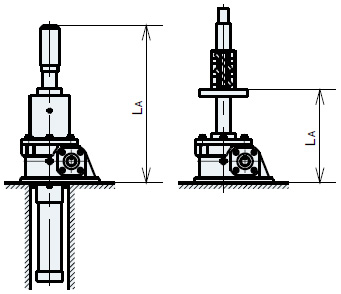
Fixed base - free shaft end
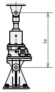
Clevis support on both ends

Fixed base - shaft end support
| Reference Distance | Stroke | Metal fittings dimensions | Clevis dimensions |
判定:
Check the allowable screw shaft rotation speed (traveling nut only)
Check frequency of use
| Usage time | ts = ST/(V×1000) = | [min] | |
| Percentage duty cycle (%ED) | %ED = [round trip/Hr] x 2 x usage time x 100/60 = | [%ED] |
判定:
Expected life calculation (Trapezoidal Screw type)
| 年間総走行距離 | Ly = ST×2×[往復/Hr]×[Hr/日]×[日/年]×10-6 = | [km] |
| Expected lifespan | Z = (JWM050以下:5km, JWM100以上:1km)/Ly = | [年] |
Expected life calculation (Ball screw type)
| 等価荷重 | PE = (W0×Sf×2+W1)/3 = | [kN] |
| Ball screw dynamic load capacity | C = | [kN] |
| Short stroke correction factor | fs = | |
| 運転条件係数 | fd = | |
| 焼入硬度補正係数 | fh = | |
| 寿命補正係数 | f1 = (PE×fd)/(C×fh×fs) = | |
| B10寿命総走行距離 | L10 = 250/f13 = | [km] |
| 年間総走行距離 | Ly = ST×2×[往復/Hr]×[Hr/日]×[日/年]×10-6 = | [km] |
| Expected lifespan | Z = L10/Ly = | [年] |
Expected life calculation (High lead ball screw type)
Please contact us separately regarding the calculation of expected life for high lead types.
Selection results
形番
:
必要入力容量
:
[kW]
Reduction ratio
:
<Caution>
This selection is based on theoretical calculations and does not guarantee the results.
Please fully understand the calculation formula for this selection, and allow for some leeway in the calculation results.
The final decision on the equipment to be used is up to the customer.

