technical data Synchronous Belts and Belt Sprockets design data
Guide flange
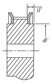
Pulley dimensions when using standard flanges
Dimensional tolerance of flange mating part
| Mating part dimension df' | 25 or less | Over 25 and under 50 | Over 50 and under 100 | Over 100 and under 180 |
|---|---|---|---|---|
| Tolerance mm | -0.02 -0.05 |
-0.02 -0.06 |
-0.02 -0.07 |
-0.02 -0.12 |
Stepped part length
| Type (pitch) | P3M | P5M | P8M | P14M |
|---|---|---|---|---|
| Step length Lf' mm | 2.0 | 2.2 | 2.6 | 5.0 |
Flange display method
AS type...Material: Aluminum
SS type...Material: Steel
AF type...Material: Aluminum
SF type...Material: Steel
AF type...Material: Aluminum
SF type...Material: Steel
Display example
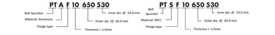
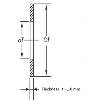
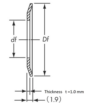
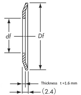
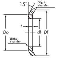
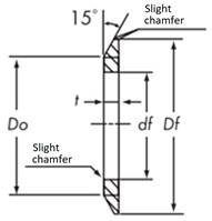
General shape and standard dimensions
| Types (pitch) |
Thickness t | Outer diameter Df Minimum |
Inner diameter df |
||
|---|---|---|---|---|---|
| Recommended value | Commonly used thickness | ||||
| Press Type | Cutting Type | ||||
| P2M | 1.0 | 1.6 | 1.0 ~ 1.6 | Do + 4 | Do - 5 |
| P3M | Do + 4.5 | ||||
| P5M | 2.0 | 1.0 ~ 2.0 | Do + 6.3 | Do - 8 | |
| P8M | 1.6 | 2.5 | 1.6 ~ 2.5 | Do + 8 | Do - 10 |
| P14M | - | 4.0 | 4.0 ~ 5.0 | Do + 14 | Do - 20 |
Depending on the standard flange used, the outer or inner diameter may differ from that shown in the table above.
Press Type
Cutting Type
Guide flange installation
Flange fixing
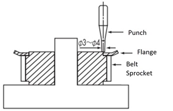
Crimping method
Press flanges and machined flanges are usually secured by caulking with a punch as shown in the diagram below.
The number of crimps must comply with the following standards:
| Tip diameter mm | 30 or less | Over 30 and under 50 | Over 50 and under 120 | Over 120 and under 250 |
|---|---|---|---|---|
| Number of rivets | 4 | 8 | 12 | 16 |
Note
- - Place the pulley on a flat surface and crimp the flange with a crimping punch.
- - When crimping the side opposite the hub, insert the hub into a cylindrical jig placed on the board and crimp in a stable position.
Other fixing methods
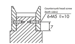
Screw fastening method
The turning flanges of large tooth count pulleys such as P8M and P14M may be fixed to the pulley body with flat head screws depending on how they are used.
The number of flat head screws in the table below is the minimum number.
| Tip diameter mm | 120 or less | Over 120 and under 250 | Over 250 and under 450 | Over 450 and under 650 |
|---|---|---|---|---|
| Number of screws | 4 | 6 | 8 | 12 |
Knurling method
A method of knurling and crimping on a lathe is also used.
Pulley tooth width
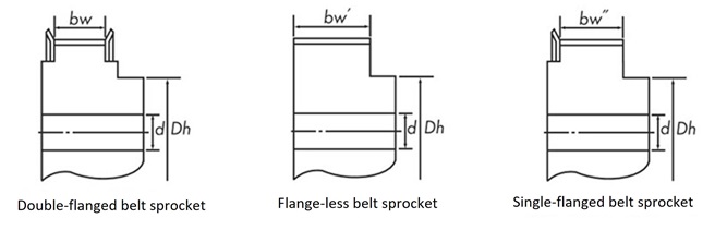
Belt width and pulley tooth width
| Types (pitch) |
Belt width mm |
Pulley tooth width (reference value) | ||
|---|---|---|---|---|
| With flanges on both sides bw |
Without flange bw' |
Single flange bw'' |
||
| P2M | 4 | 5.0 | 9.0 | 7.0 |
| 6 | 7.5 | 11.5 | 9.5 | |
| 10 | 12.0 | 16.0 | 14.0 | |
| P3M | 6 | 7.5 | 11.5 | 9.5 |
| 10 | 12.0 | 16.0 | 14.0 | |
| 15 | 17.0 | 21.0 | 19.0 | |
| P5M | 10 | 11.6 | 16.0 | 13.8 |
| 15 | 16.6 | 21.0 | 18.8 | |
| 25 | 27.6 | 32.0 | 29.8 | |
| P8M | 15 | 16.8 | 22.0 | 19.4 |
| 25 | 27.8 | 33.0 | 30.4 | |
| 40 | 43.8 | 49.0 | 46.4 | |
| 60 | 64.8 | 70.0 | 67.4 | |
| P14M | 40 | 43.0 | 53.0 | 48.0 |
| 60 | 64.0 | 74.0 | 69.0 | |
| 80 | 85.0 | 95.0 | 90.0 | |
| 100 | 106.0 | 116.0 | 111.0 | |
| 120 | 127.0 | 137.0 | 132.0 | |
Backlash-free tooth profile
Synchronous Belts normally have backlash when meshing, but for Synchronous Belts drives that require extremely accurate rotation, such as robots, electronic component assembly machines, NC devices, printers, and plotters, we manufacture pulleys with special backlash-free tooth profiles that reduce backlash and suppress rotation Angular Misalignment, so please contact us for details.

