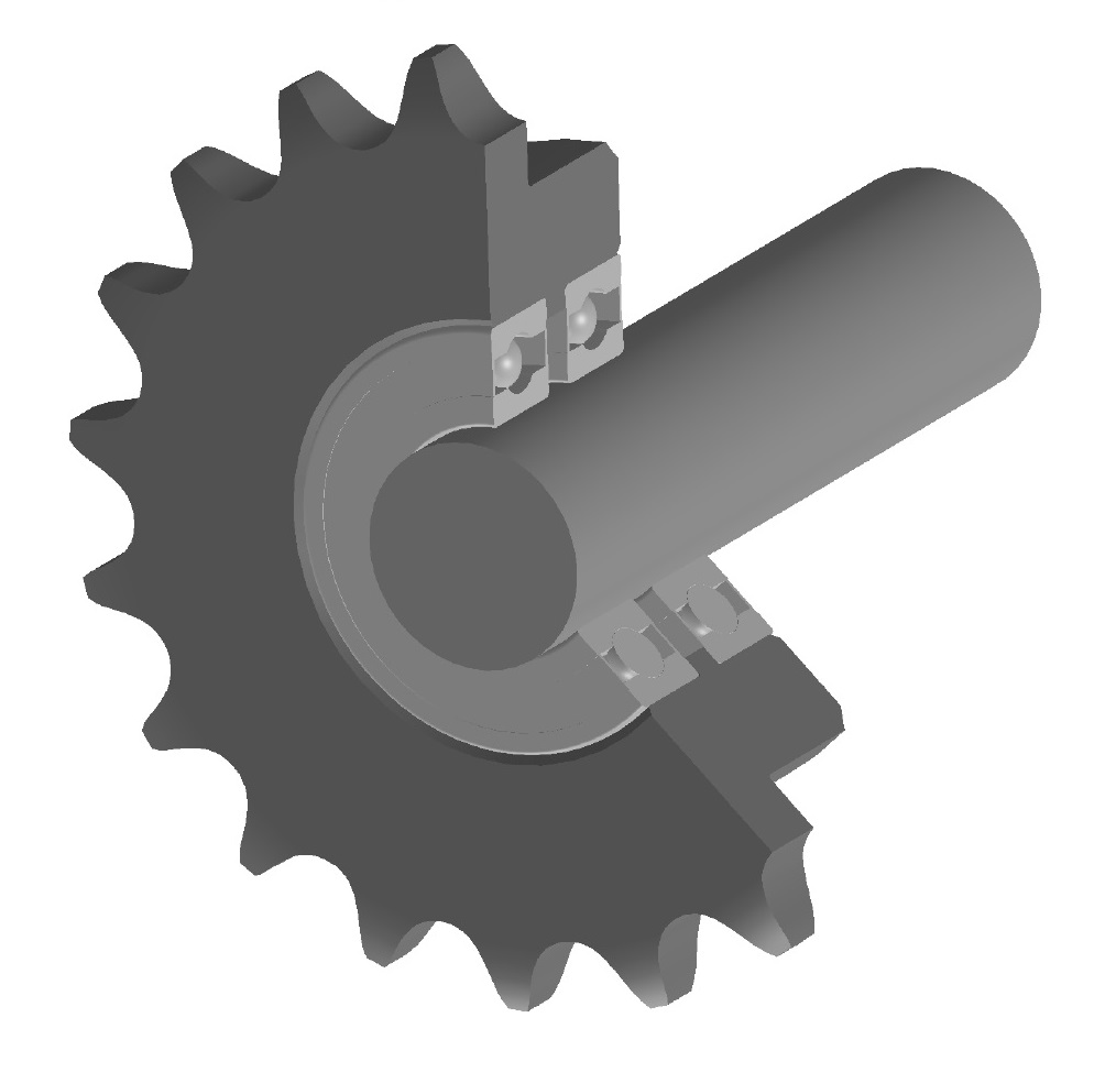
technical data Drive Sprocket Before Use
Structure, material, tooth tip specifications, shaft hole specifications
1. Structure
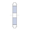
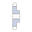
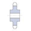
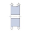
RS sprockets come in four types of structures specified by JIS.
| Model code | A-type (flat plate type) |
B type (Single hub type) |
C type (double hub type) |
SD type (single dual) |
|---|---|---|---|---|
| Structure |
|
|
|
|
| RS-HT chain (SUPER-H, HT, etc.) multiple strand Note 1 | A shape that allows two single strand chains to be hung at the same time | |||
| HB type | HC type | |||
| Use depending on the structure | It is used when attaching to a rotating body such as the center member of a torque limiter. | It is the most versatile. | Used when the key surface pressure is insufficient with the large driven sprocket or B type. | It is used by hanging two single strand chains at the same time. |
Note
1. The total tooth width (transverse pitch) of RS-HT chain multiple strand (HB type, HC type) is different from the standard.
2. Material
RS sprockets are standardized using the following materials.
| Steel type | Material |
|---|---|
| carbon steel | *Carbon steel for mechanical structures |
| Rolled steel | *General structural rolled steel |
| stainless steel | *Austenitic stainless steel |
| Resin | *Engineering plastics (Empura) |
| sintered alloy | *Sintered iron alloy (used in some RS25 sprockets) |
3. Tooth tip specifications
| Specification | |
|---|---|
| Hardened tooth tip | If you need stronger teeth and improved wear life, use sprockets with hardened teeth. All teeth of TOUGH TOOTH are hardened. |
| Dentist (raw) specifications | The tooth tips are not hardened. In the large tooth number range of RS sprockets, the tooth tips are raw. |
4. Shaft bore specifications
There are three types of shaft hole specifications for mounting a sprocket to a mating shaft:
| Series | Exterior | Specification |
|---|---|---|
| Standard pilot bore |

|
|
| Fit Bore |

|
|
| Lock Sprocket |

|
|
5. Handling roller chains and sprockets
5.1 Tooth tip hardening
Sprocket tooth tips must be hardened under the following operating conditions:
- 1. When the number of teeth is small (24 or less) and the maximum rotation speed is 1/8 or more of the maximum rotation speed listed in kW ratings table.
- 2. Small sprocket when the speed ratio is greater than 4:1.
- 3. For low speed and heavy load.
- 4. In an atmosphere that is abrasive to teeth.
5.2 Number of teeth
The larger the number of teeth on the high-speed shaft sprocket, the smoother the transmission will be.
Generally, the appropriate number of teeth is 15 or more. However, if the speed ratio is large and the number of teeth on the low-speed sprocket exceeds 120, slight wear and elongation of the chain can cause poor meshing.
Therefore, please design the high-speed sprocket so that it has fewer teeth. Even in this case, we recommend that it has 13 or more teeth.
However, if the speed is very low and there is no impact, sprockets with 12 or fewer teeth can be used.
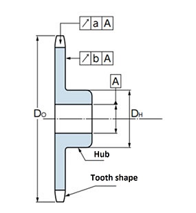
5.3 Precautions for additional processing
1. Shaft hole processing
- - Maximum bore dimensions
The maximum bore finishing dimensions are equal to or less than the maximum bore diameter listed in each dimension table.
If you are using a key other than the JIS standard, please inform us of the processing details. - ・Processing standards
Please process based on the outer diameter Do of the toothed portion or the outer diameter DH of the hub.
At this time, please make sure that the runout at tooth root a and the lateral runout at the tooth end face b are below the values in the table below.
| tooth root diameter (df) | 90 or less | Over 90 190 or less |
Over 190 Under 850 |
Over 850 1180 or less |
1180 Something that exceeds |
|---|---|---|---|---|---|
| tooth root runout a | 0.15 | 0.0008df+0.08 | 0.76 | ||
| Horizontal vibration b | 0.25 | 0.0009df+0.08 | 1.14 | ||
2. Welding of A-type sprockets
Please avoid welding a hub to an A-type sprocket as this may cause distortion due to welding and runout of the tooth end face, making it impossible to maintain quality.
Also, welding of A-type tooth-hardened sprockets may reduce their hardness, so please avoid welding them as well.
3. Machining the outer diameter of the hub
Do not perform additional machining on the outer diameter of the hub. If you wish to perform machining, please contact us.
5.4 Sprocket Surface Treatment
When plating, blackening or other surface treatment is applied to standard sprockets, please strictly observe the following.
- - Anti-rust oil and anti-rust paint have been applied, so remove them completely.
- - If hardened tooth sprockets are subjected to treatments that may cause hydrogen embrittlement, such as electrolytic plating, adequate preventative measures must be taken.
New JIS key
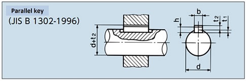
| Shaft Hole Diameter d |
Key designation dimensions Width x Height b×h |
Keyway Depth | |
|---|---|---|---|
| Axis t1 | boss d + t2 | ||
| Over 6 and under 8 | 2×2 | 1.2 | d + 1.0 |
| 8 〃 10 〃 | 3×3 | 1.8 | d + 1.4 |
| 10 〃 12 〃 | 4×4 | 2.5 | d + 1.8 |
| 12 〃 17 〃 | 5×5 | 3.0 | d + 2.3 |
| 17 〃 22 〃 | 6×6 | 3.5 | d + 2.8 |
| 20 〃 25 〃 | (7×7) | 4.0 | d + 2.3 |
| 22 〃 30 〃 | 8×7 | 4.0 | d + 3.3 |
| 30 〃 38 〃 | 10×8 | 5.0 | d + 3.3 |
| 38 〃 44 〃 | 12×8 | 5.0 | d + 3.3 |
| 44 〃 50 〃 | 14×9 | 5.5 | d + 3.8 |
| 50 〃 55 〃 | (15×10) | 5.0 | d + 5.3 |
| 50 〃 58 〃 | 16×10 | 6.0 | d + 4.3 |
| 58 〃 65 〃 | 18×11 | 7.0 | d + 4.4 |
| 65 〃 75 〃 | 20×12 | 7.5 | d + 4.9 |
| 75 〃 85 〃 | 22×14 | 9.0 | d + 5.4 |
| 80 〃 90 〃 | (24×16) | 8.0 | d + 8.4 |
| 85 〃 95 〃 | 25×14 | 9.0 | d + 5.4 |
| 95 〃 110 〃 | 28×16 | 10.0 | d + 6.4 |
| 110 〃 130 〃 | 32×18 | 11.0 | d + 7.4 |
| 125 〃 140 〃 | (35×22) | 11.0 | d + 11.4 |
| 130 〃 150 〃 | 36×20 | 12.0 | d + 8.4 |
| 140 〃 160 〃 | (38×24) | 12.0 | d + 12.4 |
| 150 〃 170 〃 | 40×22 | 13.0 | d + 9.4 |
| 160 〃 180 〃 | (42×26) | 13.0 | d + 13.4 |
| 170 〃 200 〃 | 45×25 | 15.0 | d + 10.4 |
| 200 〃 230 〃 | 50×28 | 17.0 | d + 11.4 |
| 230 〃 260 〃 | 56×32 | 20.0 | d + 12.4 |
| 260 〃 290 〃 | 63×32 | 20.0 | d + 12.4 |
| 290 〃 330 〃 | 70×36 | 22.0 | d + 14.4 |
| 330 〃 380 〃 | 80×40 | 25.0 | d + 15.4 |
| 380 〃 440 〃 | 90×45 | 28.0 | d + 17.4 |
| 440 〃 500 〃 | 100×50 | 31.0 | d + 19.5 |
Old JIS key
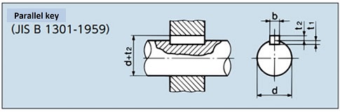
| Shaft Hole Diameter d |
Key designation dimensions Width x Height b×(t2+t1) |
Keyway Depth | |
|---|---|---|---|
| Axis t1 | boss d + t2 | ||
| 10 or more 13 or less | 4×4 | 2.5 | d + 1.5 |
| Over 13 20 | 5×5 | 3.0 | d + 2.0 |
| 20 〃 30 〃 | 7×7 | 4.0 | d + 3.0 |
| 30 〃 40 〃 | 10×8 | 4.5 | d + 3.5 |
| 40 〃 50 〃 | 12×8 | 4.5 | d + 3.5 |
| 50 〃 60 〃 | 15×10 | 5 | d + 5 |
| 60 〃 70 〃 | 18×12 | 6 | d + 6 |
| 70 〃 80 〃 | 20×13 | 7 | d + 6 |
| 80 〃 95 〃 | 24×16 | 8 | d + 8 |
| 95 〃 110 〃 | 28×18 | 9 | d + 9 |
| 110 〃 125 〃 | 32×20 | 10 | d + 10 |
| 125 〃 140 〃 | 35×22 | 11 | d + 11 |
| 140 〃 160 〃 | 38×24 | 12 | d + 12 |
| 160 〃 180 〃 | 42×26 | 13 | d + 13 |
| 180 〃 200 〃 | 45×28 | 14 | d + 14 |
| 200 〃 224 〃 | 50×31.5 | 16 | d + 15.5 |
| 224 〃 250 〃 | 56×35.5 | 18 | d + 17.5 |

