technical data linear actuator Zip Chain Actuator Handling
handling
Installation precautions
- 1. Grease is used for lubrication, so grease may splash. Take sufficient care to avoid the effects of the surroundings. (If you are concerned about grease splashing, we recommend using a bellows.) Grease may drip, especially when used in a suspended position.
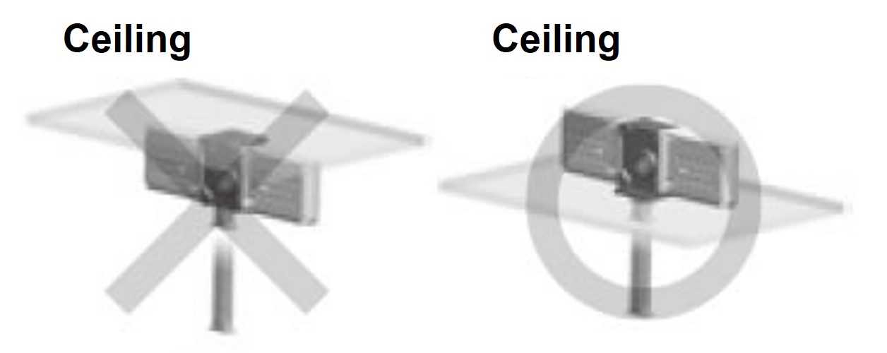
- 2. It can be mounted in lifting, horizontal, and hanging directions. However, when mounting in horizontal or hanging directions, if the weight of the main body and the weight (force) of the transported object are applied to the mounting bolts themselves, the equipment may be damaged. Please install it in a way that the mounting bolts do not bear the load. (Fig. 1)
Hanging installation
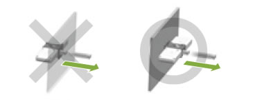
Horizontal installation when pushing out
Horizontal installation, tension
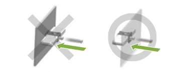
Figure 1 Possible installation directions (example)
- 3. For motor-less machines, when installing the motor, reducer, main body, etc., prepare a sturdy base that is rigid enough to ensure proper installation and has a safety factor that will prevent deviations in centering accuracy during installation even when the maximum load is applied. Also, provide a separate mechanism to align the motor output shaft and ZCA input shaft center height. If the shaft center heights are misaligned, a rotating bending force will act on the motor output shaft and ZCA input shaft, which may cause damage to the shaft.
- 4. When driving the shaft with a chain or belt, make sure that the overhang load acting on the shaft is below the allowable overhang load. (See the selection page for details.)
- 5. For installation, use the four mounting taps on the drive unit and End fitting to securely fasten the product. (Mounting bolts are not included.) The mounting bolt size should be in accordance with Table 1, and the bolt strength classification should be 10.9 (JIS B 1051) or higher. Consider the bolt screw-in depth appropriate to the strength of the mounting material.
Table 1 Mounting bolt sizes
Model number Drive unit (bottom) Drive unit (side) End fitting ZCA25 M5 M5 M4 ZCA35 M6 M6 M5 ZCA45 M8 M8 M8 When installing, be sure to apply bolt locking measures to prevent loosening.
- 6. Do not stop the product at the stroke end under any circumstances. Doing so may cause serious damage to the inside of the product.
- 7. Make sure that the load applied to the main body acts on the same axis as the direction of movement of Zip Chain. If the direction or position of the load is inappropriate, Zip Chain may be subjected to bending or lateral loads, which could cause damage (Figure 2). Be sure to install a linear guide in the direction of movement to prevent Zip Chain from being subjected to direct lateral loads or bending or twisting moments.
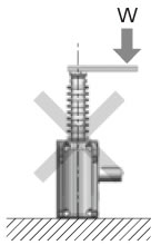
Figure 2
- 8. Zip Chain are made up of many interlocking links that form a columnar shape. A columnar chain may become slightly twisted or warped.
- 9. Please allow sufficient stroke margin for the stroke you are using. If the stroke range is exceeded, the stopper may be damaged, the chain may come off, or End fitting may collide with the drive unit, damaging the main body.
- 10. When installing a limit switch to regulate the stroke, set it taking into account the coasting amount.
- 11. Please check the rotation direction of the shaft and the direction of movement of Zip Chain beforehand. (See the external dimensions.) Incorrect rotation direction may damage the main body. If a motor is installed, please note that the direction of movement of the chain relative to the electrical wiring will differ depending on the speed.
- 12. Make sure that foreign matter such as dust or chips does not adhere to or get mixed into Zip Chain, drive openings, etc. This accelerates wear and can be a major cause of chain breakage or damage to moving parts.
- 13. If the drive unit is installed with its bottom facing downwards, the shaft keyway will be nearly facing upwards (see Figure 3) at the lowest stroke limit. However, when synchronizing, etc., there will be some deviation due to individual differences in backlash, etc., so please provide a separate mechanism to adjust the phase. If the phase is incorrect, the load on each ZCA unit will increase, which may cause the chain to buckle or the shaft to break. When adjusting the phase, use a Tsubaki Power-Lock or similar tool to adjust the tip height at the lowest Zip Chain position.
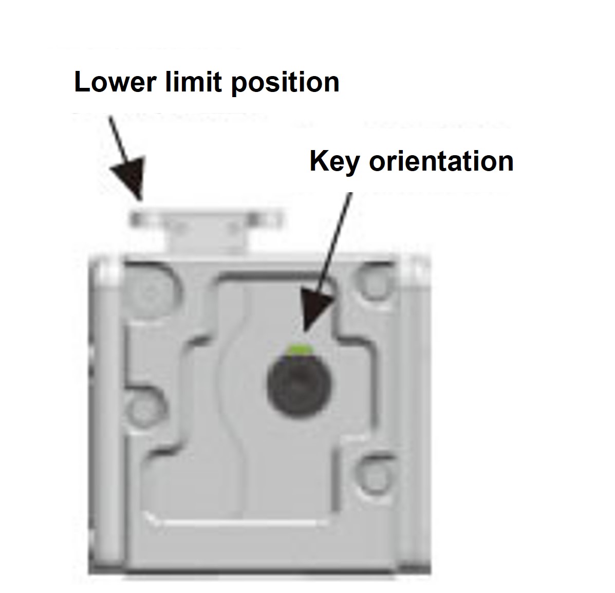
Figure 3
- 14. When using this product in a suspension device, be sure to install safety devices and safety fences in case the chain breaks, and never enter under the suspended object. We will not manufacture or sell this product if there is a risk of personal injury.
- 15. Bellows for lifting or hanging installation will be damaged early if they are installed horizontally. For horizontal installation, a dedicated bellows incorporating special parts is required. These can be manufactured separately, so please contact us.
- 16. Condensation and humidity may cause the grease to deteriorate prematurely and leak. If you plan to use the product in a special environment, please consult us when requesting a quote.
- 17. Do not perform any additional work on Zip Chain Actuator.

