technical data linear actuator Zip Chain Actuator Selection
Selection table
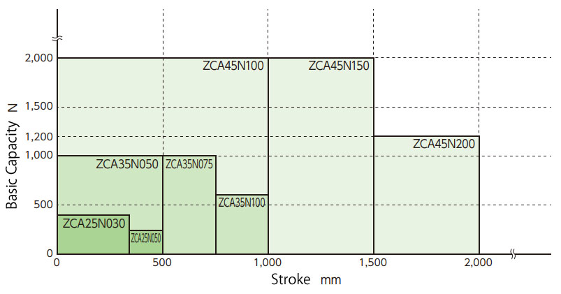
The graph on the right shows the relationship between stroke and basic capacity.
Check the required thrust and stroke per ZCA unit using this graph to determine the model number.
If detailed consideration is required, please check the calculation below.
Selection method
Machinery used... Machine configuration, number of ZCA units used, operating environment, etc.
Load..... Load characteristics, load or workpiece mass, drive source, drive method, etc.
Mounting shape: Mounting direction (upward, horizontal, hanging), linear guide type
Operating speed..... ZCA required speed
Strokes...The strokes you will actually use
1. Calculation of the correction load Fs
Considering the nature of the load, calculate the corrected load Fs by referring to Service factor (Table 1).
Corrected load Fs N{kgf} = Required thrust PN{kgf} × Service factor Sf
Table 1 Service factor
| Load Nature | Usage example | Service factor Sf |
|---|---|---|
| Smooth operation without shocks Load inertia small |
Conveyor switching | 1.0~1.3 |
| Operation with slight impact Load inertia medium |
Various transfer devices Various lifter lifting |
1.3~1.5 |
2. Calculation of the required thrust Fs1 per unit
The required thrust Fs1 per unit is calculated from the corrected load Fs.
In the case of linked operation, refer to Multiple factor (Table 2) for calculation.
Thrust per ZCA unit Fs1 N{kgf} = Corrected load Fs N{kgf} ÷ (Number of linked units × Multiple factor Fg)
Table 2: Multiple factor
| Number of linked units (units) | 1 unit | 2 units | 4 units |
|---|---|---|---|
| Multiple factor Fg | 1.0 | 0.83 | 0.69 |
3. Choose between no drive unit, Hypoid Motor, or TERVO.
4. Select a model number
From the model list, confirm that the thrust Fs1 per unit is equal to or less than the basic capacity of the ZCA. Allow some margin for the stroke to be used.
[If no drive unit is selected]
From the model list, provisionally select a model number based on the thrust and allowable stroke per unit. Proceed to step 5 onwards.
[If you select Hypoid Motor or TERVO]
From the model list, tentatively select a model number that satisfies the thrust per unit, chain operating speed, and allowable stroke.
Please proceed to section 9 onwards. For a list of models, please refer to the list for models with Hypoid Motor (here) and models with TERVO (here).
5. Maximum speed
Make sure you are below the maximum speed.
6. Check the required input rotation speed
The required input rotation speed is calculated from the operating speed.
N = V×60/K N: Input rotation speed r/min V: Operating speed mm/s K: Zip Chain movement distance mm per input shaft rotation (Table 3)
7. Check the required input torque
Calculate the required input torque.
T = Fs1×Dp 2×1000×η + To
T: Required input torque N・m{kgf・m}
Fs 1: Required thrust per unit N{kgf}
D p: Sprocket pitch diameter mm (Table 3)
η: Overall efficiency of ZCA (Table 3)
To: Average no-load operating torque N・m{kgf・m} (Table 3)
Table 3 Ability table
| Model | ZCA25 | ZCA35 | ZCA45 |
|---|---|---|---|
| Overall efficiency η | 90% | 90% | 90% |
| *Average no-load operating torque To N・m{kgf・m} | 0.62{0.063} | 1.63{0.17} | 5.85{0.6} |
| Input shaft travel per revolution K mm | 95.3 | 142.9 | 240 |
| Sprocket pitch diameter Dp mm | Φ30.92 | Φ46.48 | Φ78.0 |
*This is the average torque required to continuously rotate the input shaft under no load.
There is torque fluctuation due to meshing at each pitch of the chain.
8. Consideration of allowable overhang load
When the shaft is driven by a chain, gear, toothed belt, V-belt, etc., check that the overhang load is within the allowable value.
OHL: Overhanging Load N{kgf}
f: Transmission element coefficient (Table 4)
Lf: Coefficient depending on the load application position (Table 5)
T: Required input torque N・m{kgf・m}
D: Pitch circle diameter of sprocket, gear, pulley, etc. m
Allowable OHL ≧ 2×T×f×Lf D
Table 4 Transmission element coefficients (f)
| Chain | Gear Toothed Belt | V-belt |
|---|---|---|
| 1.0 | 1.25 | 1.5 |
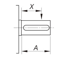
Table 5. Load coefficient (Lf) depending on load application position
| X/A | 0.25 | 0.5 | 0.75 | 1.0 |
|---|---|---|---|---|
| Lf | 0.9 | 1.0 | 1.15 | 1.25 |
Table 6 Allowable overhang load
| Model | ZCA25 | ZCA35 | ZCA45 |
|---|---|---|---|
| Allowable overhang load N{kgf} | 638{65.0} | 946{96.4} | 2065{210.5} |
9. Select Options
Select the option according to your usage conditions.
- ・Mounting base
- ·cap
- ・Bellows
- ・Greasing plate
10. Deciding on the model number
11. Calculating the required input capacity (without motor)
Required input capacity P kW = T×N/9550
Note:
If the average no-load operating torque accounts for 25% or more of the required input torque, the torque fluctuations caused by the chain's unique meshing action will have a significant effect. To ensure smooth operation, select a torque that is 1.5 times the average no-load operating torque (Table 3).
Precautions when selecting required input torque
If the ZCA is arranged in a straight line as shown in the diagram below, make sure that the input torque from the drive source is below the allowable input shaft torque.
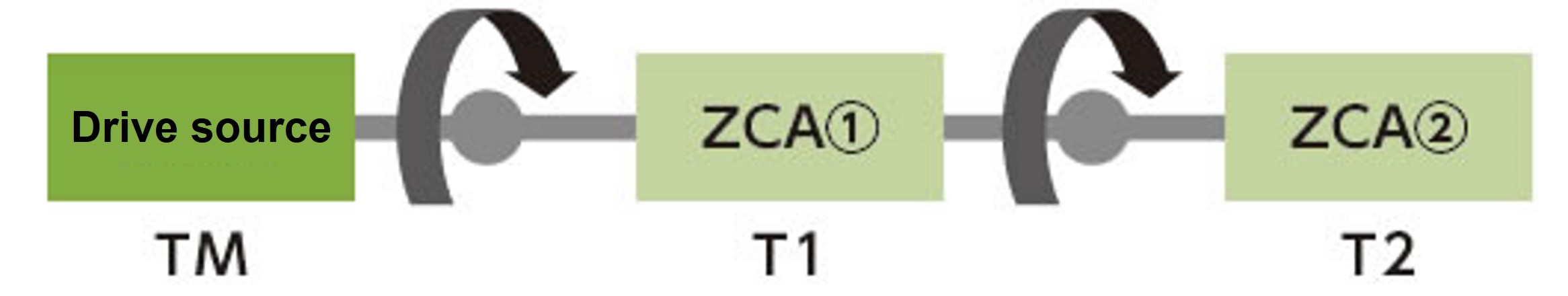
The required input torque for two units is transmitted to the input shaft of the ZCA (1) on the drive source side.
Make sure that the torque of these two units is below the allowable input shaft torque.
Required input torque T1 for ZCA (1) only
Required input torque T2 for ZCA (2) only
Required torque of driving source TM = T1 + T2 < Allowable input shaft torque
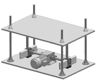
Selection example
Machine used: Two ZCA lifting devices used, inside the factory (normal temperature, no dust)
Required thrust..... Light impact, 1200N {122kgf}/2 units, small gear motor with brake is installed separately and connected with a coupling
Mounting type: 4 guide poles (used for lifting)
Operating speed: 250mm/s (constant speed: no acceleration or deceleration)
Stroke.....450mm
Power supply....200V/60Hz
| SI units |
|---|
ZCA
Motor (60Hz)
Coupling
|
| {gravity unit} |
|---|
ZCA
Motor (60Hz)
Coupling
|
If position control is required, use a motor with an encoder or a servo motor.
(If you require a motor with an encoder, please contact us separately.)
This selection example is just an example, so please refer to the dedicated catalog when selecting couplings, Miter Gear Box, and motors.
Drive unit
Hypoid Motor TA/TR series
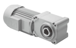
- -This is a compact, small-sized geared motor that uses a highly efficient hypoid gear and has a reduced height.
- - Easy to use with unique grease leakage prevention measures, and when used in conjunction with an encoder-equipped model, multi-point positioning control is also easy.
Miter Gear Box
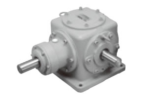
- ・ Miter Gear Box are used when multiple Zip Chain Actuator are operated in sync.
- -We offer a wide variety of standard models in terms of size, shaft arrangement, speed ratio, material, etc.
ECHT-FLEX Coupling
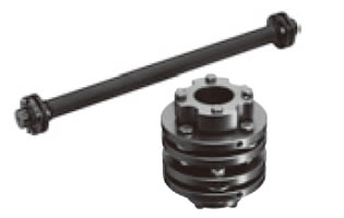
- - A lubrication-free, high-precision coupling that is also ideal for driving servo motors.
- ・Supports a wide range of shaft fastening methods, including keyway, clamp, and taper lock, as well as precise shaft hole processing in 1mm increments.

