technical data linear actuator Power Cylinder
Eco Series Servo Type Servomotor Assembly Procedure (For installation by the customer)
Direct motor connection
Please prepare a servo motor. (The output shaft can be used with or without a keyway.)
Install the motor so that the coupling mounting hole on the motor flange faces upward (45 and 105mm frames only).
Wipe off any rust, dust, or rust-preventive oil from the motor shaft.
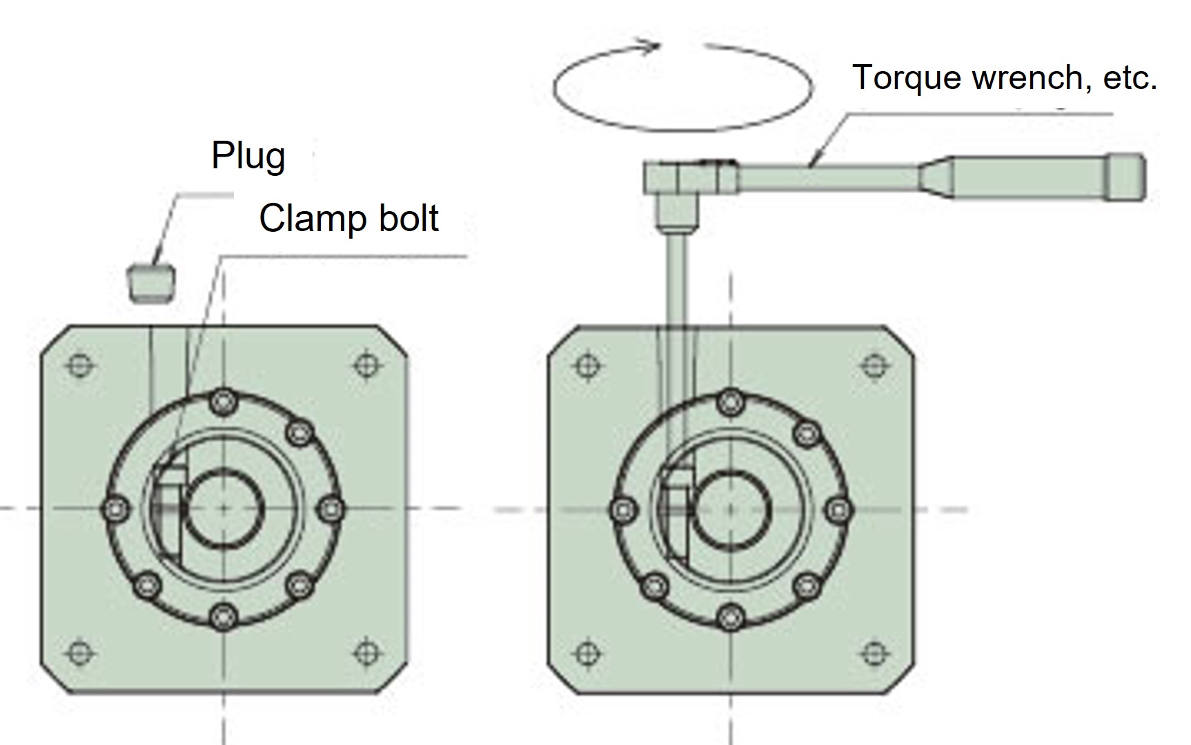
Loosen the clamp bolt of the coupling.
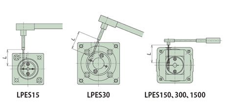
Remove the plug from the coupling case, turn the input shaft, and align the head of the coupling clamp bolt with the plug hole.
*For LPES30, the torque wrench must be inserted at an angle as shown in the diagram below.
Insert the motor shaft smoothly into the coupling.
*When the motor is rotated in the direction of rotation, the phase with the clamp bolt may shift.
Be careful not to insert the motor shaft at an angle.
After inserting the spigot part completely, install it with the motor mounting bolts.
Use a torque wrench to tighten the clamp bolt of the coupling to the specified tightening torque.
Attach the removed plug to the coupling case.
*Please refer to Instruction Manuals for details.
| Model number | Coupling Bolt size |
Tightening torque N・m{kgf・m} |
L dimension mm |
|---|---|---|---|
| LPES15 | M2 | 0.5{0.04} | 30 |
| LPES30 | M2.5 | 1.0{0.10} | 40 |
| LPES150 | M4 | 3.8{0.39} | 60 |
| LPES300 | 70 | ||
| LPES1500 | M6 | 12{1.22} | 90 |
With precision planetary reducer
1. When the motor shaft is round
Install the reducer so that the motor mounting surface is on top.
Wipe off any rust, dust, or rust-preventive oil from the motor shaft.
Remove the plug from the adapter and turn the input shaft to align the bolt head with the plug hole.
Use a hex wrench or similar tool to check that the set bolt is loose.
Insert the motor shaft smoothly into the input shaft hole. At this time, be careful not to insert the motor shaft at an angle, as this may cause it to gall against the shaft hole and prevent proper installation.
After the spigot is fully inserted, secure the motor to the adapter with the appropriate tightening torque.
Use a torque wrench or similar tool to tighten the set bolts on the input shaft to the tightening torque shown in the table below. At this time, please be careful not to tighten them below the specified tightening torque, as this may lead to malfunctions such as slippage of the motor shaft due to the set bolts loosening. Do not apply a loosening preventative such as Loctite to the set bolts. This may prevent the proper tightening torque from being obtained and result in insufficient tightening.
Install the plug. This completes the motor installation.
Tightening the clamp bolt
If an unexpected impact occurs, it is possible that the clamp mating part may slip. Please consider installing a separate safety mechanism for lifting drives, etc.
Clamp bolt tightening torque table
| Bolt size | M3 | M4 | M5 | M6 | M8 | M10 |
|---|---|---|---|---|---|---|
| Tightening torque N・m{kgf・m} |
1.9 {0.18} |
4.3 {0.44} |
8.7 {0.89} |
15 {1.50} |
36 {3.70} |
71 {7.20} |
*Bolt tightening torque should be within the range of the above value x 1.0 to 1.2.
Motor mounting bolt tightening torque table
| Bolt size | M3 | M4 | M5 | M6 | M8 |
|---|---|---|---|---|---|
| Tightening torque N・m{kgf・m} |
1.1 {0.11} |
2.5 {0.26} |
5.1 {0.52} |
8.7 {0.89} |
21 {2.10} |
*Bolt tightening torque should be within the range of the above value x 1.0 to 1.2.
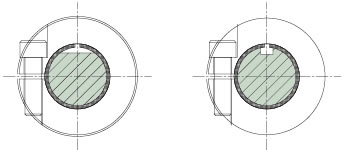
2. Mounting a motor with a key
Motor shafts with keys can be used as clamp types in the same way as round shafts by removing the key.
Set the motor shaft keyway (D cut), each slit, and set bolt in the positions shown in the diagram on the right.
For other parts, please attach to the reducer using the same procedure as for the round shaft.
Important points to note when selecting (Eco Series, Servo Type)
- This cylinder does not have a rotation prevention mechanism. A rotational force is generated in the rod due to the thrust, so be sure to take measures to prevent rotation on the mating device side.
The rotational force generated in the rod at maximum thrust is as shown in the table below.Model number LPES15 LPES30 LPES150 LPES300 LPES1500 Rod rotation force
N・m{kgf・m}0.16{0.016} 0.32{0.031} 1.60{0.16} 3.19{0.33} 26.6{2.72} - - This cylinder does not have a load retention mechanism built into the cylinder body. If a dangerous situation is anticipated when the cylinder stops or when the product breaks down, use a servo motor with an electromagnetic brake to retain the load, or install an external brake mechanism. The same applies if positional deviation is a problem when using it in a lifting device or for horizontal use.
- ・ Power Cylinder are designed for indoor use. To avoid problems such as rust, please store them in a good indoor environment. Be careful of humidity. Installing them in a place with sudden temperature changes will cause condensation, which may lead to malfunctions or rust, so please be careful.
- - Do not store or use in a corrosive atmosphere. Also, do not use in a flammable atmosphere.
- - Do not use the product in a sealed container or other location where heat dissipation cannot be expected, as this may cause a malfunction.
Installation precautions (Eco Series, Servo type)
- - Use a trunnion mount or flange mount (only available for LPES150 and below) to install the main body.
If the product will be subject to swing motion, select End fitting I-shaped or U-shaped End fitting. If a lateral load is applied, install a guide to prevent direct lateral loads or bending moments. - - When installing with a trunnion mount, it can be installed horizontally or vertically.
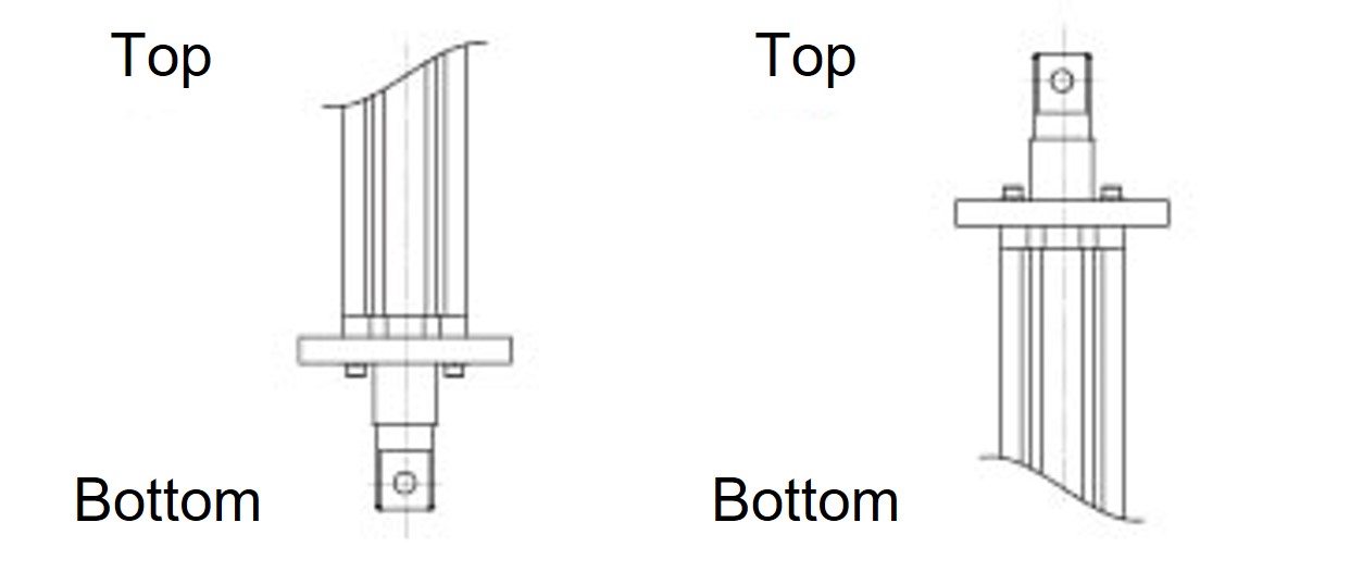
- - When installing with a flange mount, install it vertically (see the diagram on the right).
*For flange mounts of LPES300 or higher types, please contact us.
*Flange mounting is not possible if bellows are attached. - - If you are using the cylinder in a stationary position without any swinging motion, please select (1) flange mount or (2) trunnion mount + foot mount. Horizontal and vertical mounting is also possible (□45 frame only).
- - When using with Long travel length and in a horizontal position, please support the bottom end of the frame separately as shown in the diagram below.
In this case, do not secure the frame and support base.

Frame end support
(Cannot be fixed)
Trunnion Mount
Flange Mount

(1) Flange mount

(2) Trunnion mount + foot mount
Precautions for use (Eco Series Servo Type)
- ・This cylinder does not have an overload protection mechanism built into the cylinder body, so please provide protection against overload, overcurrent, and overvoltage in the servo driver (servo amplifier). Also, please make sure that the device connected to Power Cylinder is strong enough to withstand the maximum torque of the servo motor.
- ・This cylinder does not have a manual operation shaft due to its structure, so please adjust the cylinder position at a slow speed using a servo driver (servo amplifier).
- • The screw shaft of this cylinder is coated with Daphne Eponex SR No. 2 at the time of shipment, but periodic lubrication is necessary.
Please refer to the table on the right for grease refill cycles.
The amount of grease to be applied is 10 to 15 g per 100 mm of stroke.
We also offer JWGS100G (sold separately) as maintenance grease.
(Please see here.)*Apply grease to the outer surface of the rod in accordance with the lubrication cycle to prevent the oil film from breaking.
Use the same grease as the screws.*Please determine the lubrication cycle based on your usage conditions.
Frequency of use Grease Cycle 1001 round trips/day or more Every 1 to 3 months 501-1000 round trips/day Every 3 to 6 months 101-500 round trips/day Every 6 months to 1 year ~100 round trips/day or less Every 1 to 1.5 years
Ideal for maintenance of Linipower Jack and Power Cylinder!

(100g included)
形番:JWGS100G

