technical data linear actuator Power Cylinder Selection
Selection: Eco Series Servo Type
Input shaft moment of inertia
| Basic model number | reducer size |
Moment of inertia per stroke x 10-4 kg m 2 | |||||
|---|---|---|---|---|---|---|---|
| 100 | 200 | 300 | 400 | 500 | 600 | ||
| LPES15F | - | 0.086 | 0.102 | 0.119 | - | - | - |
| LPES30F | - | 0.134 | 0.151 | 0.168 | - | - | - |
| LPES30R3 | 042 | 0.045 | 0.047 | 0.049 | - | - | - |
| LPES30R4 | 0.038 | 0.039 | 0.041 | - | - | - | |
| LPES30R5 | 0.035 | 0.036 | 0.037 | - | - | - | |
| LPES30R7 | 0.033 | 0.033 | 0.033 | - | - | - | |
| LPES30R9 | 0.032 | 0.032 | 0.032 | - | - | - | |
| LPES30RA | 0.031 | 0.032 | 0.032 | - | - | - | |
| LPES150F | - | 1.039 | 1.166 | 1.292 | 1.418 | 1.545 | 1.671 |
| LPES150R3 | 060 | 0.275 | 0.290 | 0.304 | 0.318 | 0.332 | 0.346 |
| LPES150R4 | 0.205 | 0.213 | 0.221 | 0.229 | 0.237 | 0.244 | |
| LPES150R5 | 0.172 | 0.177 | 0.182 | 0.187 | 0.192 | 0.197 | |
| LPES150R7 | 0.151 | 0.154 | 0.156 | 0.159 | 0.162 | 0.164 | |
| LPES150R9 | 0.143 | 0.144 | 0.146 | 0.148 | 0.149 | 0.151 | |
| LPES150RA | 0.140 | 0.142 | 0.143 | 0.144 | 0.145 | 0.147 | |
| LPES300F | - | 1.720 | 1.846 | 1.973 | 2.099 | 2.225 | 2.352 |
| LPES300R3 | 060 | 0.351 | 0.365 | 0.379 | 0.393 | 0.407 | 0.421 |
| LPES300R4 | 0.247 | 0.255 | 0.263 | 0.271 | 0.279 | 0.287 | |
| LPES300R5 | 0.199 | 0.204 | 0.209 | 0.214 | 0.219 | 0.224 | |
| LPES300R7 | 0.165 | 0.168 | 0.170 | 0.173 | 0.175 | 0.178 | |
| LPES300R9 | 0.151 | 0.153 | 0.154 | 0.156 | 0.157 | 0.159 | |
| LPES300RA | 0.147 | 0.148 | 0.150 | 0.151 | 0.152 | 0.154 | |
| LPES300R3 | 075 | 0.801 | 0.815 | 0.829 | 0.843 | 0.857 | 0.871 |
| LPES300R4 | 0.587 | 0.595 | 0.603 | 0.611 | 0.619 | 0.627 | |
| LPES300R5 | 0.539 | 0.544 | 0.549 | 0.554 | 0.559 | 0.564 | |
| LPES300R7 | 0.485 | 0.488 | 0.490 | 0.493 | 0.495 | 0.498 | |
| LPES300R9 | 0.461 | 0.463 | 0.464 | 0.466 | 0.467 | 0.469 | |
| LPES300RA | 0.457 | 0.458 | 0.460 | 0.461 | 0.462 | 0.464 | |
| Basic model number | reducer size |
Moment of inertia per stroke x 10-4 kg m 2 | ||||||
|---|---|---|---|---|---|---|---|---|
| 200 | 300 | 400 | 500 | 600 | 800 | 1000 | ||
| LPES1500F | - | 12.513 | 13.155 | 13.797 | 14.438 | 15.080 | 16.363 | 17.647 |
| LPES1500R3 | 075 | 2.000 | 2.072 | 2.143 | 2.214 | 2.286 | 2.428 | 2.571 |
| LPES1500R4 | 1.262 | 1.302 | 1.342 | 1.382 | 1.423 | 1.503 | 1.583 | |
| LPES1500R5 | 0.971 | 0.996 | 1.022 | 1.048 | 1.073 | 1.125 | 1.176 | |
| LPES1500R7 | 0.705 | 0.718 | 0.732 | 0.745 | 0.758 | 0.784 | 0.810 | |
| LPES1500R9 | 0.594 | 0.602 | 0.610 | 0.618 | 0.626 | 0.642 | 0.658 | |
| LPES1500RA | 0.565 | 0.572 | 0.578 | 0.584 | 0.591 | 0.604 | 0.616 | |
| LPES1500R3 | 100 | 4.640 | 4.712 | 4.783 | 4.854 | 4.926 | 5.068 | 5.211 |
| LPES1500R4 | 3.522 | 3.562 | 3.602 | 3.642 | 3.683 | 3.763 | 3.843 | |
| LPES1500R5 | 3.211 | 3.236 | 3.262 | 3.288 | 3.313 | 3.365 | 3.416 | |
| LPES1500R7 | 2.875 | 2.888 | 2.902 | 2.915 | 2.928 | 2.954 | 2.980 | |
| LPES1500R9 | 2.724 | 2.732 | 2.740 | 2.748 | 2.756 | 2.772 | 2.788 | |
| LPES1500RA | 2.695 | 2.702 | 2.708 | 2.714 | 2.721 | 2.734 | 2.746 | |
| LPES1500R3 | 140 | 11.000 | 11.072 | 11.143 | 11.214 | 11.286 | 11.428 | 11.571 |
| LPES1500R4 | 8.547 | 8.587 | 8.627 | 8.667 | 8.708 | 8.788 | 8.868 | |
| LPES1500R5 | 8.065 | 8.090 | 8.116 | 8.142 | 8.167 | 8.219 | 8.270 | |
| LPES1500R7 | 7.469 | 7.482 | 7.495 | 7.508 | 7.521 | 7.547 | 7.574 | |
| LPES1500R9 | 7.239 | 7.247 | 7.255 | 7.263 | 7.271 | 7.286 | 7.302 | |
| LPES1500RA | 7.191 | 7.198 | 7.204 | 7.210 | 7.217 | 7.230 | 7.242 | |
Note: The moment of inertia does not include the moment of inertia of the servo motor.
Allowable frequency of use and Percentage duty cycle
Percentage duty cycle is the percentage of operation time per 30 minutes, based on a 30-minute period.
Percentage duty cycle is calculated using the formula on the right.
The allowable number of starts for the Eco Series servo type is determined by the heat generated by the motor and Ball screw /bearing. The above values should be used as a guideline as they vary depending on the stroke and thrust used. Also, they do not take into account the lifespan of the cylinder. However, this is subject to the condition that the servo motor is operated within its rated capacity.
| Number of startups | 15 times/minute |
|---|---|
| Percentage duty cycle | 50%ED |
*Normally indoors refers to a location that is not exposed to wind, rain, or water, and where the dust level is the same as that inside a general factory.
Percentage duty cycle (%ED) = Operation time per cycle Operation time per cycle + Down time x 100
lifespan
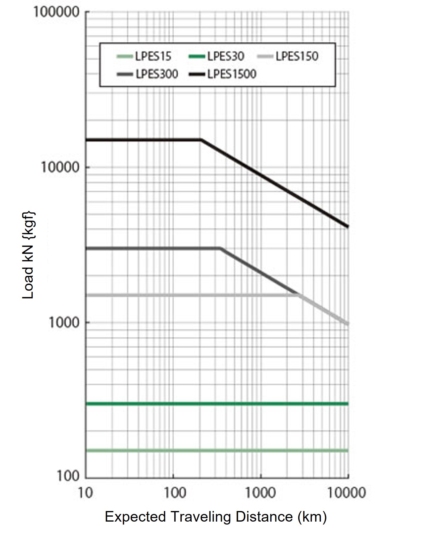
The lifespan of Ball screw is determined by flaking caused by fatigue on the rolling surface. Please check this expected travel distance graph for an approximate lifespan. However, if there is a lot of impact or if proper lubrication and maintenance are not performed, the expected travel distance will be significantly shorter.
Expected travel distance (km) = Actual load stroke (m) × frequency of use (times/day) × number of operating days/year × 10-3 × expected number of years
The graph on the right is based on L10 life.
L10 life is the lifespan that 90% or more of the total can achieve, expressed in travel distance.
When selecting Power Cylinder based on its lifespan, please select the model number from this graph.
For example, if the expected travel distance is 1000km and the actual load is 5000N {510kgf}, the required Power Cylinder is LPES1500.
*Select the servo motor capacity from the mount code table so that "actual load < generated thrust".
If the load fluctuates significantly midway through the stroke, calculate the equivalent load (P M) using the formula below.
Also, for LPES30 or below, the expected travel distance is over 10,000 km.
PM = PMIN + 2×PMAX 3
P M: Equivalent load N{kgf}
P MIN: Minimum load N{kgf}
P MAX: Maximum load N{kgf}
Expected travel distance