technical data linear actuator Linipower Jack Handling
Installation
Jack mounting surface
The mounting surface of the jack is painted to prevent rust. If painting of the mounting surface is not required, please contact us.
Installation direction
It is safer to use the lifting type for lifting loads and the hanging type for hanging loads.
In addition, since the jack has an open structure, there is a risk that grease and separated oil from the grease may scatter or fall. Please prepare a grease receiver, etc. In particular, when using a jack for hanging, there is a risk that grease may drip down the screw shaft.
Installation direction
Use the four mounting holes on the jack's gear case and secure it with mounting bolts (mounting bolts are not included).
For the jack mounting bolt size, refer to Table 1. Normally, use mounting bolts with a strength classification of 8.8 or 10.9.
If the mounting bolt itself is subjected to load as shown in Figure 1, use a bolt with a strength classification of 10.9 or higher.
Table 1 Mounting bolt sizes
| Model number | Mounting holes | Bolt size |
|---|---|---|
| JW002 | 4-Φ7 | M6 |
| JW005 | 4-Φ7 | M6 |
| JW010 | 4-Φ9 | M8 |
| JW025 | 4-Φ11 | M10 |
| JW050 | 4-Φ18 | M16 |
| JW100 | 4-Φ22 | M20 |
| JW150 | 4-Φ22 | M20 |
| JW200 | 4-Φ26 | M24 |
| JW300 | 4-Φ33 | M30 |
| JW500 | 4-Φ42 | M39 |
| JW750 | 4-Φ42 | M39 |
| JW1000 | 6-Φ42 | M39 |
Figure 1
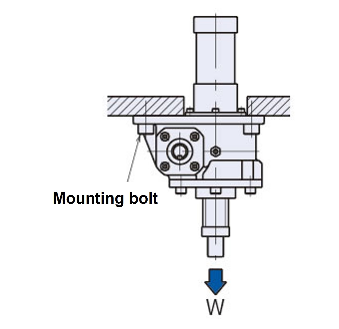
*The weight of the jack and the hanging load act as a tensile load on the mounting bolt.
Connection with motor and reducer
When installing the jack itself, as well as the motor, reducer, etc., please prepare a sturdy base with a safety factor that will prevent the centering accuracy during installation from being affected even when the maximum load is applied, so that proper installation can be performed.
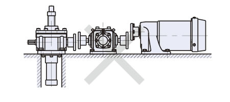
Also, be sure to properly center the transmission shaft connected to the input shaft (Fig. 2).
When driving with a floating shaft, vibrations may occur depending on the rotation speed, which may result in malfunction, so please carefully consider the shaft rigidity and coupling backlash.
Figure 2
Mounting End fitting
When attaching End fitting to the end of a screw shaft, be sure to apply a locking agent to the threaded part of the shaft end.
Rotational torque acts on the screw shaft, causing End fitting to fall off, so please take the following measures.
[Apply adhesive to prevent screws from loosening]
To prevent screws from loosening, please use the following brands or equivalent.
When applying adhesive, please follow the handling precautions of each manufacturer.
Screw locking adhesive
| Manufacturer | Brand |
|---|---|
| Nihon Lock Tight | #262、271 |
| Three Bond | #1307N |
[Fixed with a set screw]
After tightening End fitting, secure it with the included setscrew (hexagon socket head bolt) to prevent it from loosening.
Prevents screw shaft from rotating
The screw shaft (or nut in the case of a traveling nut specification) generates a rotational force due to the thrust, so it is necessary to prevent rotation. The screw shaft rotation torque at basic capacity is listed in the basic specifications for each type. If operating without a guide at the tip or if attaching a pulley or sprocket to pull a rope or chain, etc., please use the anti-rotation specification (symbol M).
The anti-rotation specification for JWH (High lead ball screw type) is available as a special order, so please contact us.
However, since the traveling nut cannot be manufactured with a rotation prevention mechanism, please provide a rotation prevention mechanism on the device side.
Limit switch settings
The limit switch installed to adjust the stroke should be set taking into account the amount of coasting of the jack.
The coasting distance varies depending on the installation condition and the weight of the load being transported, so please plan for the maximum coasting distance. Also, please install a mechanical stopper or similar within the stroke range just in case.
Position detection unit settings
If you are using an optional position detection unit (internal LS, potentiometer, rotary encoder), stroke adjustments are not made at the factory, so be sure to make adjustments before operation. Control units such as potentiometers and rotary encoders output various signals by measuring the number of rotations of the input shaft, so if you rotate the screw shaft while the input shaft is fixed, the settings will be shifted, so after adjustment, do not rotate the screw shaft (or the nut in the case of traveling nut specifications).
When adjusting the internal LS, operate it manually or by inching, taking great care not to exceed the stroke range of the jack. Exceeding the stroke limit may cause the screw shaft to fall off or the bellows to be damaged, so please be careful.
Bellows jack for horizontal or inclined use
When using a bellows jack horizontally or at an angle (including use involving swinging), special measures are required to prevent the screw shaft from getting caught in the bellows, damaging the bellows or causing malfunctions in the jack.
The X dimension (MIN and MAX values) of the bellows jack may be longer, or the outer diameter of the bellows may be larger.
If you need to confirm dimensions when purchasing, please contact us.
Bellows with traveling nut specifications are available as special orders, so please contact us.
Precautions
- ⚠ (1) The screw covers of jacks with a basic capacity of 49.0 kN {5 tf} or less are made of hard PVC pipes. Never use the screw covers to lift, suspend, or transport the jack, as this may cause it to fall.
- ⚠ (2) When selecting and using a jack, allow a certain amount of leeway for the stroke to be used. Using the jack beyond its stroke range may result in the screw shaft falling off or damage to the jack. The JWM (Trapezoidal Screw type) does not have a stopper on the screw shaft, so the screw shaft will fall out if the stroke range is exceeded. The JWB (Ball screw type) and JWH (High lead ball screw type) are equipped with a stopper, but this is to prevent the screw shaft from falling out during manual operation during installation. When installing, take care to prevent the screw shaft from rotating or moving under its own weight. If falling out is unavoidable, use a jack with a rotation prevention mechanism.
- ⚠ (3) For JWB (Ball screw type) and JWH (High lead ball screw type), do not manually operate the input shaft while a load is applied. The load may cause the input shaft to rotate, which is dangerous. When using JWB (Ball screw type) and JWH (High lead ball screw type) in a vertical position, their efficiency is so high that the load may cause the jack to reverse, so never operate them manually.
- (4) Do not stop the jack by hitting it under any circumstances. Doing so may cause serious damage to the inside of the jack.
- (5) For equipment that cannot tolerate oil, such as food processing machinery, install an oil pan or other damage prevention device to prevent grease from splashing or falling.
- (6) The holes through which the screw covers and screw shafts pass through the base should be as small as possible to ensure a large contact area between the jack mounting surface and the base.
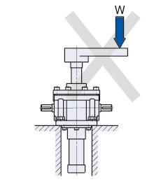
- (7) The load applied to the jack should be coaxial with the jack's screw axis. If the load direction or position is inappropriate, bending or lateral loads may be applied to the jack, which may cause damage. (Figure 3)
If lateral loads or other forces are applied, please install a guide to ensure that the jack is not subjected to direct lateral loads or bending moments.
Figure 3