technical data High-speed lifter Lift Master Handling
Operation and inspection procedures
This section describes general handling of Lift Master.
For details, please refer to Instruction Manuals included with the product.
driving
- - When using Lift Master, be sure to observe allowable load, allowable overhang load, and allowable lifting speed.
If this is exceeded, the main body may be damaged or the transported item may fall. - ・Never use the lifter outside of the stroke range, including coasting, under any circumstances. Deviation from the stroke range may result in damage to the equipment. Do not subject the lifter to any impact under any circumstances.
- - Do not allow foreign matter such as dust or chips to adhere to or get mixed in with screws, moving parts, or detection parts. These can accelerate wear, shorten the life of screws, damage moving parts, and lead to serious accidents. Be sure to take measures to prevent foreign matter from entering Lift Master main unit.
In addition, a safety fence should be installed around Lift Master to prevent people from entering the space below the object being lifted. - - Design the sequence circuit so that the motor's holding brake is always activated to prevent the load from dropping when the motor is stopped.
- ・Do not stop the product by hitting it against something under any circumstances. Doing so may cause serious damage to the inside of the product.
- - Use Lift Master only when a compressive load is applied.
| ⚠ caveat |
|
|---|
Maintenance and inspection
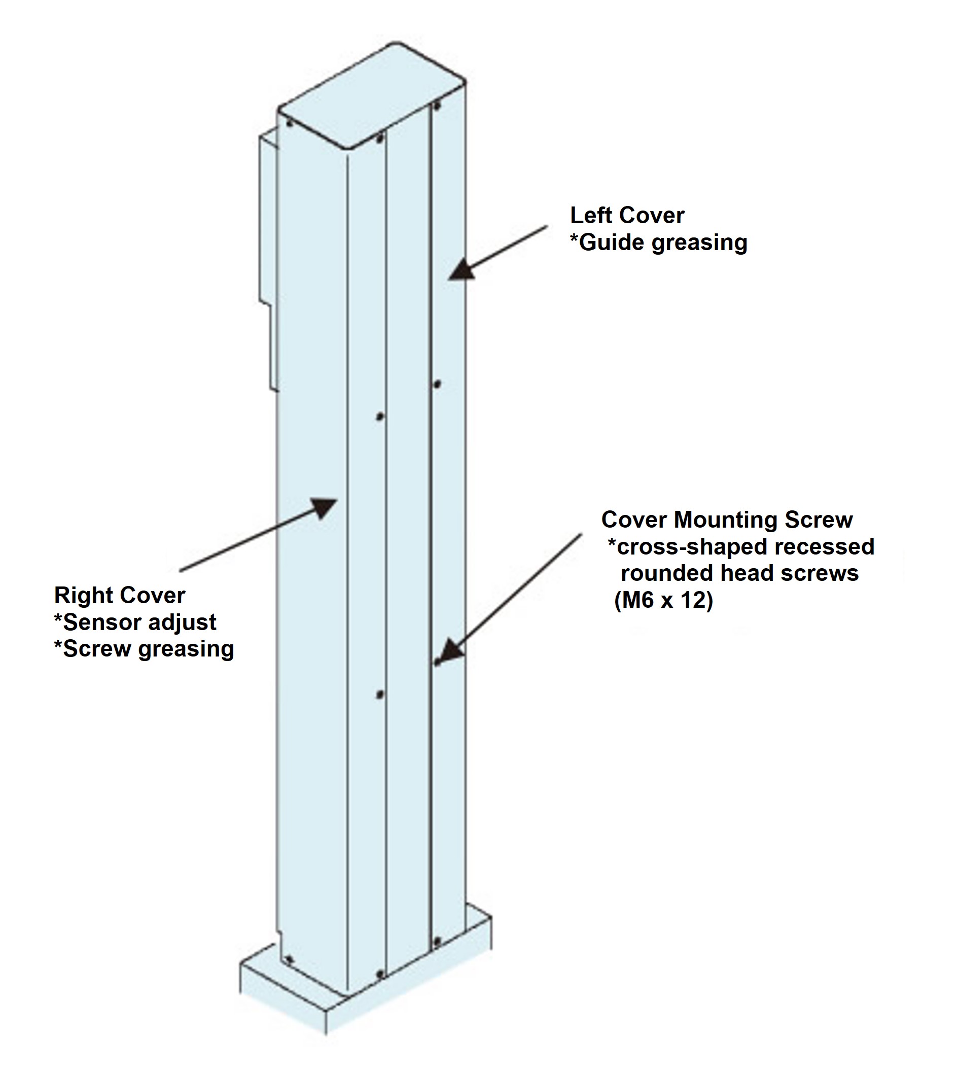
1. Remove the cover
Cover R must be removed when changing the position of the upper/lower limit sensor or greasing the screw shaft, and cover L must be removed when greasing the guide.
When removing the cover, remove the mounting screws (M6 x 12 cross recessed pan head screws) before removing the cover.
*The diagram below is for reference only. Please refer to the delivery diagram for the actual external dimensions.
2. Greasing
(Threaded part)
Move it to its maximum stroke, wipe off the old grease, and then apply it directly to the screw shaft using a grease gun or brush.
(Guide part)
Grease is supplied through the grease nipple.
Add enough new grease until the old grease is drained out.
After greasing, perform a break-in run and remove any excess grease before starting operation.
<Reference diagram of grease points>
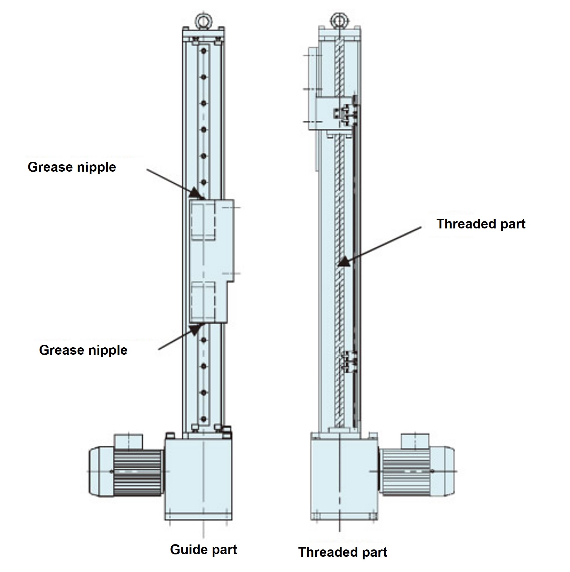
*The above diagram is for reference only. Please refer to the delivery diagram for the actual external dimensions.
| item | Usage category | |||
|---|---|---|---|---|
| Threaded part | Guide section | |||
| Grease used (Grease used at time of shipment) |
Daphne Eponex SR No.2 (Manufactured by Idemitsu Kosan Co., Ltd.) |
|||
| Grease Cycle | Trapezoidal Screw | Ball screw | 3 months | |
| Frequency of use: 50-100 times/day | 1 month | 3 months | ||
| Frequency of use: 10-50 times/day | 3 months | 3 months | ||
| Frequency of use: 1-10 times/day | 6 months | 6 months | ||
| Greasing amount | 10–15 g (per 100mm stroke) |
LME200,500 | 4.5~6.5g | |
| LME1000 | 9.0~13.5g | |||
3. Maintenance and inspection of three-phase motors (Hypoid Motor)
For maintenance and inspection of Hypoid Motor, please refer to the attached Hypoid Motor Instruction Manuals.
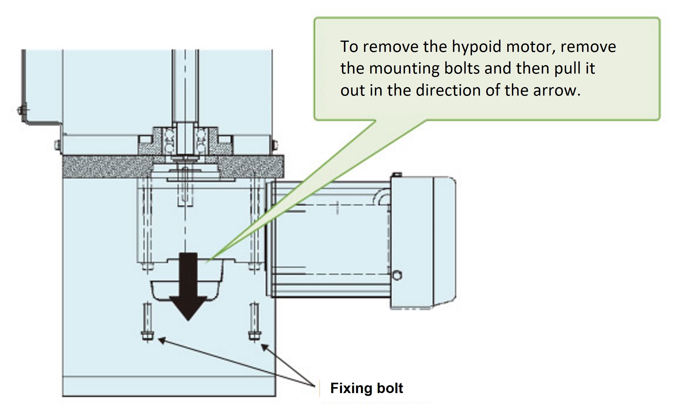
<Work Procedure>
- (1) Be sure to turn off the power before starting this procedure.
- (2) Disconnect the Lift Master main unit from the customer's equipment so that there is no load on the Lift Master main unit. At that time, prevent the unit from falling by lifting up the base plate of Lift Master.
- (3) Loosen the four bolts securing Hypoid Motor.
At this time, if all four bolts are removed, Hypoid Motor may fall out, so leave one of the bolts loose to prevent the motor from falling out. - (4) Remove all bolts while holding Hypoid Motor to prevent it from falling out.
- (5) Remove Hypoid Motor downwards.
- (6) Align the key phase of Hypoid Motor hollow shaft with the key phase of the screw shaft end, and then assemble Hypoid Motor.
(Reassemble in the reverse order of disassembly.)
4. Servo motor-equipped reducers, servo motor maintenance and inspection
For maintenance and inspection of the reducer, please refer to the attached Instruction Manuals. For servo motors, please refer to the manufacturer's Instruction Manuals.
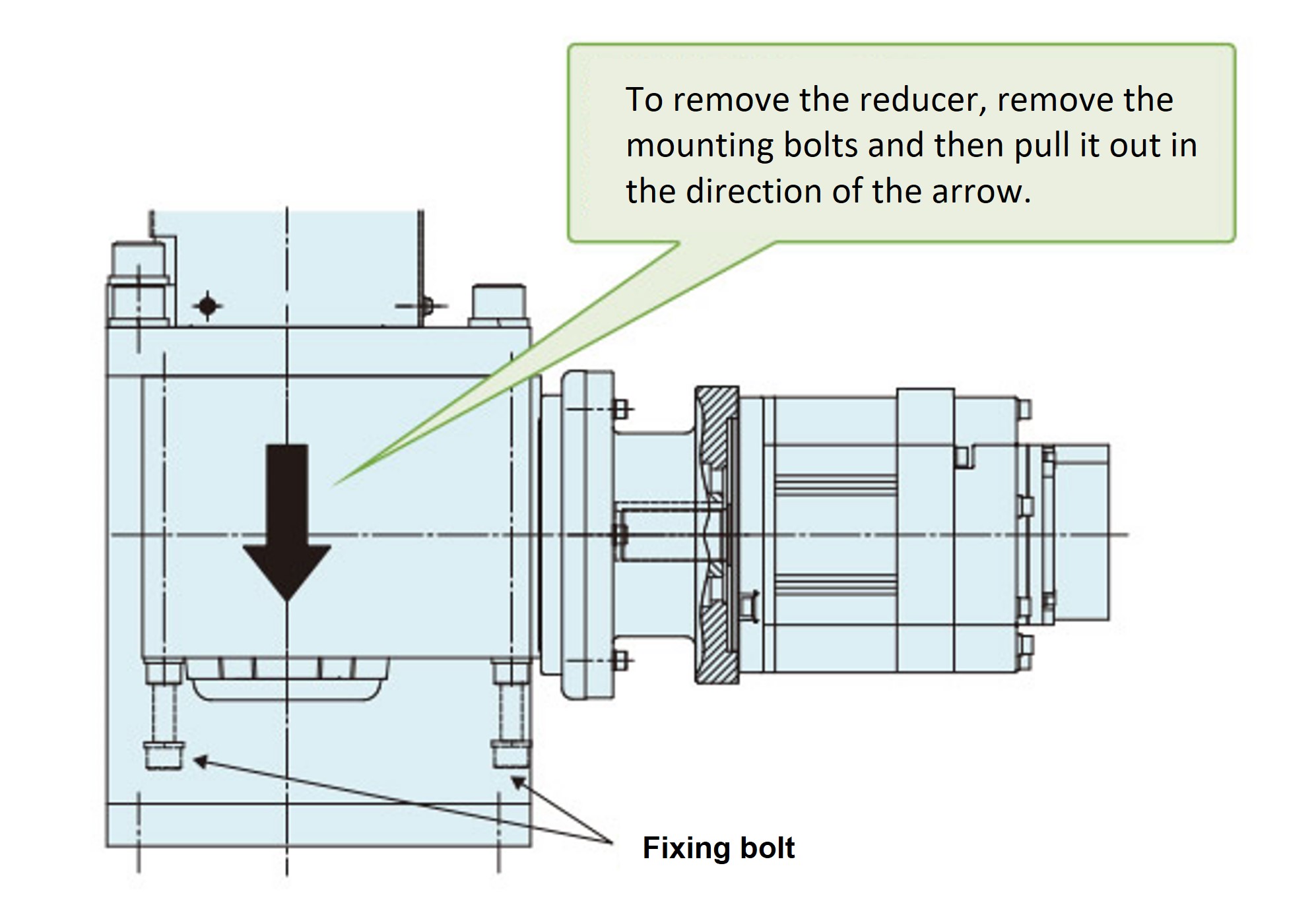
4-1. How to replace reducer
<Work Procedure>
- (1) Be sure to turn off the power before starting this procedure.
- (2) Disconnect Lift Master unit from the customer's equipment and ensure that there is no load on Lift Master unit.
In this case, please take measures to prevent Lift Master from falling, such as lifting up the base plate. - (3) Loosen the four bolts that secure the reducer.
At this time, if all four bolts are removed, the reducer may fall out, so leave one of the bolts loose to prevent it from falling out. - (4) Remove all the bolts while holding the reducer to prevent it from falling out.
- (5) Remove the reducer downwards.
- (6) Align the key phase of the hollow shaft of the reducer with the key phase of the end of the screw shaft, and then assemble the reducer.
(Reassemble in the reverse order of disassembly.)
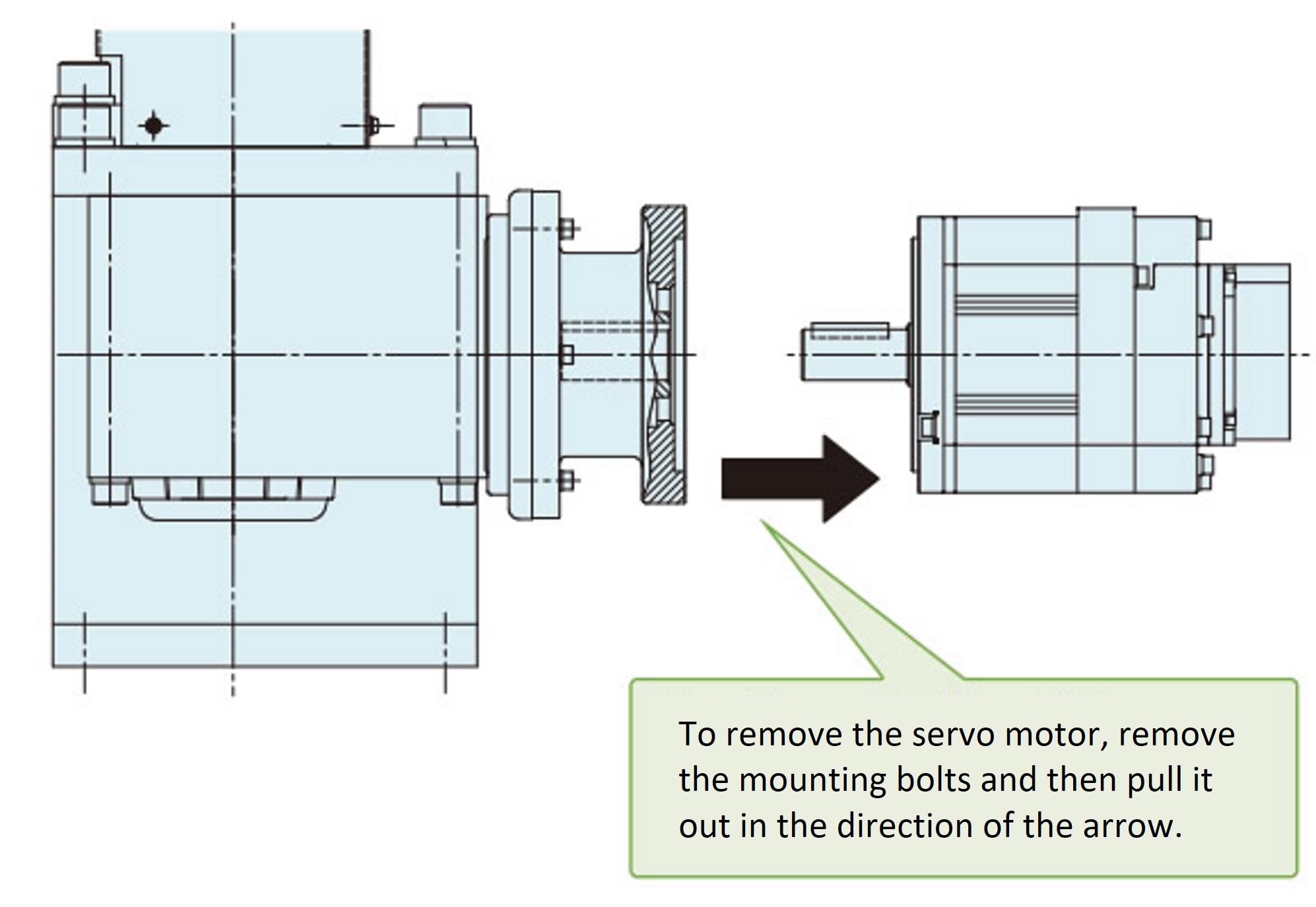
4-2. How to replace the servo motor
<Work Procedure>
- (1) Be sure to turn off the power before starting this procedure.
- (2) Disconnect Lift Master unit from the customer's equipment and ensure that there is no load on Lift Master unit.
In this case, please take measures to prevent Lift Master from falling, such as lifting up the base plate. - (3) Loosen the four bolts that secure the servo motor and remove it.
- (4) Remove the servo motor in the direction of the arrow.
- (5) Check that the key is attached to the servo motor, align the phase with the key groove on the reducer side, and then assemble the servo motor.
(Reassemble in the reverse order of disassembly.)