technical data High-speed lifter Lift Master Handling
Receiving, transporting and setting up
This section describes the general handling of Lift Master.
For details, please refer to Instruction Manuals included with the product.
Inspection upon receipt
When you receive Lift Master, please check the following items.
If you have any problems or questions, please contact the store where you purchased the product.
- - Check whether the [1] TYPE (model number), [2] MFG NO. (manufacturing number), and [3] DRAWING NO. (drawing number) listed on the nameplate match those you require (Figure 1).
- - Is there any damage caused by transportation?
- -Are there any loose screws or nuts?
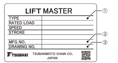
(Figure 1) How to read the nameplate
When making an inquiry, please provide the following information: [1] TYPE (model number), [2] MFG NO. (manufacturing number), and [3] DRAWING NO. (drawing number).
Installation
1. Installation precautions
| ⚠ caveat |
|
|---|
2. Installation Procedure
(1) Beforehand, check that the mounting surface is sufficiently rigid and that it is level using a spirit level.
*Ensuring that the mounting surface is level will make it easier to achieve accurate standing of Lift Master.
| ⚠ caveat |
|
|---|
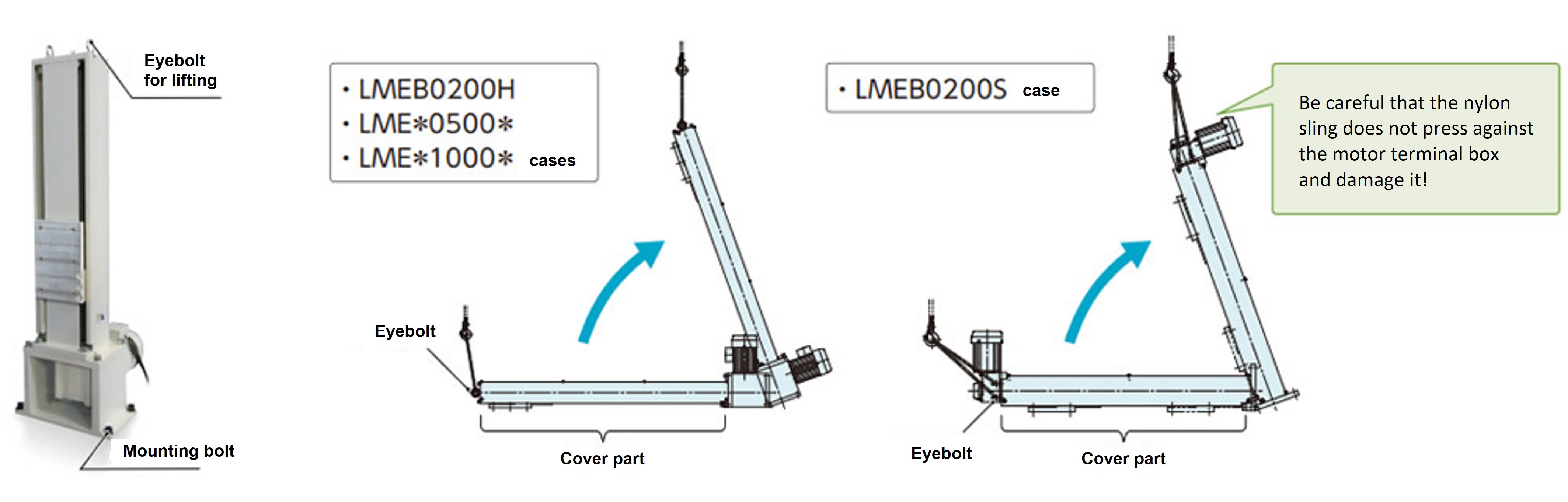
(2) When lifting the main body, first disassemble the packaging box, then hang a nylon sling or other lifting device on the eyebolt on the top of the main body, and then lift the main body upright.
Lift the main body while it is still standing and move it to the installation position.
*When lifting the main body, check the mass using the delivery drawing and use the appropriate lifting equipment.
* The diagram below is for reference only. Please refer to the delivery drawing for the actual external dimensions.
| ⚠ caveat |
|
|---|
(3) Temporarily secure the lifter body with four M16 bolts (strength classification 10.9 or higher).
*Please prepare the mounting bolts yourself.
| ⚠ caveat |
|
|---|
(4) Adjust the level as necessary.
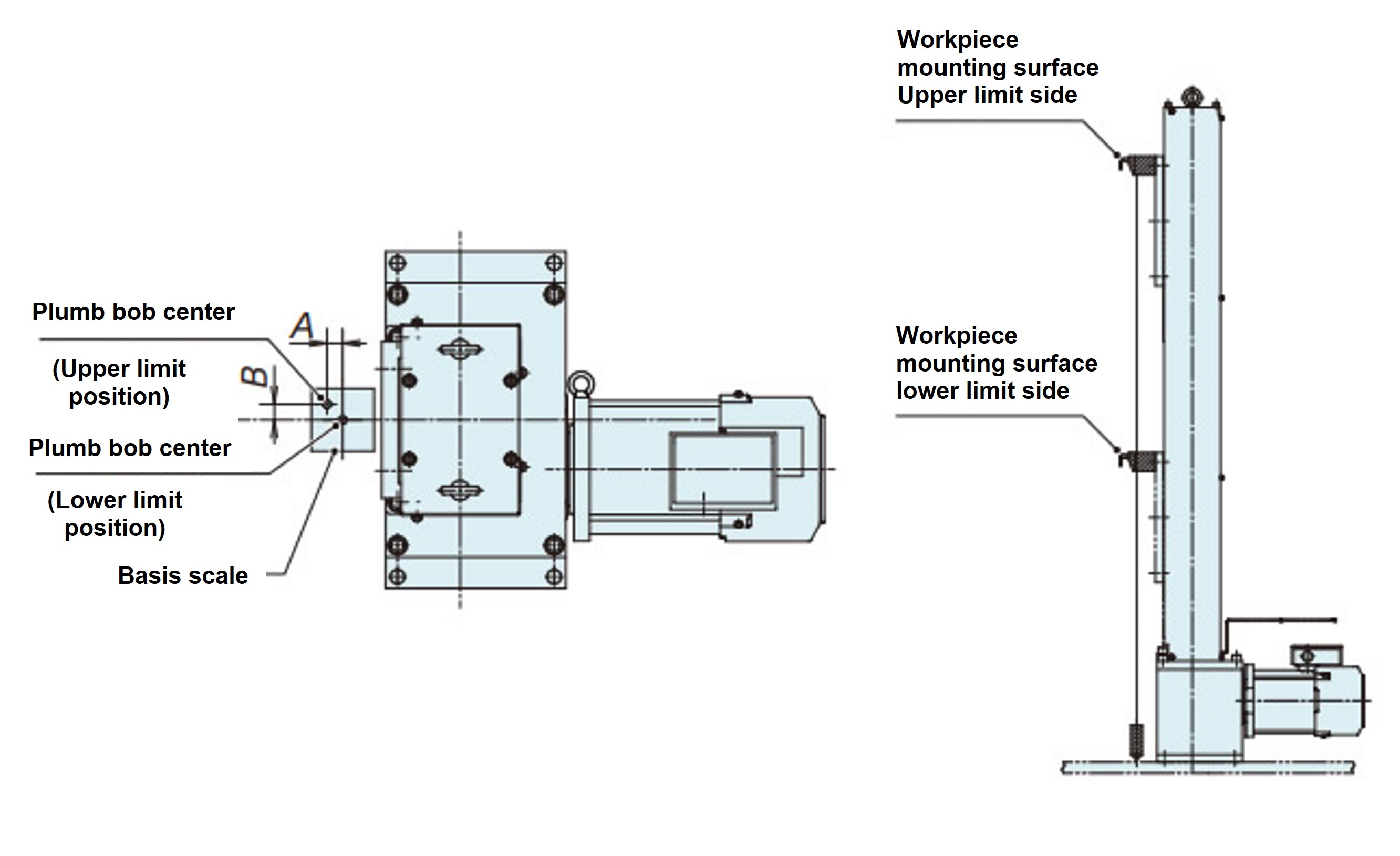
*To check the accuracy of Lift Master, use a plumb bob or similar tool as shown in the diagram on the right.
(Adjust so that the difference between dimensions A and B is within ±1 mm (as a guide) at the upper and lower stroke limits.)
(5) After adjusting the level, tighten the mounting bolts. (Recommended tightening torque: 289 N・m)
(6) Before carrying out a test run, make sure that the mounting bolts are properly tightened.
[Plumb bob image]