technical data Mechanical protector
Shock Guard TGX available
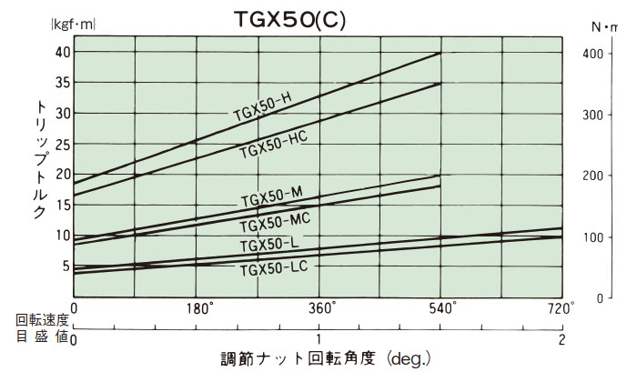
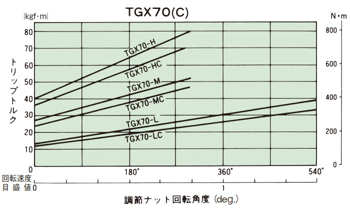
1. Trip torque setting
- (1) When shipping, all Shock Guard TGX products are set to the minimum torque value. Make sure that the indicator points to zero on the torque scale.
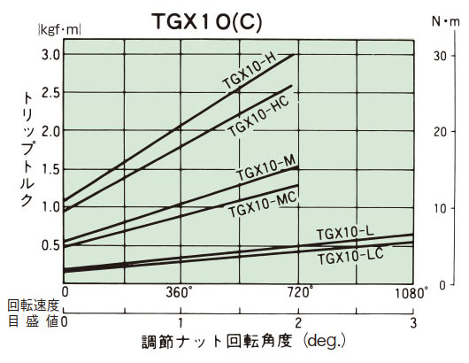
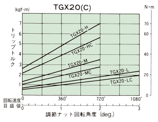
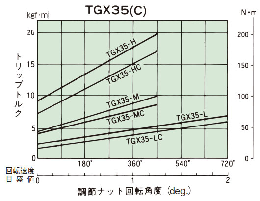
(Please refer to Instruction Manuals.) - (2) From the tightening amount-torque correlation diagram (table below), read the tightening angle of the adjustment nut (bolt) that corresponds to the predetermined trip torque, and then tighten it. One graduation on the torque scale is 60°. Initially, set it about 60° in front of the tightening value read from the correlation diagram, then attach it to the machine and perform a trip test, gradually increasing the angle until you reach the optimum trip torque. The trip torque of the product will not necessarily match the tightening amount-torque correlation diagram below, so use it as a guide only.
- (3) Once the torque setting is complete, tighten the lock screw into the adjustment nut to prevent it from loosening.
- (4) Do not turn the adjustment nut (bolt) beyond the maximum torque scale. When tripped, the disc spring will no longer have any room for deflection and will enter a locked state. Please refer here for the tightening torque of the lock screw and other precautions.
Tightening amount-torque correlation diagram
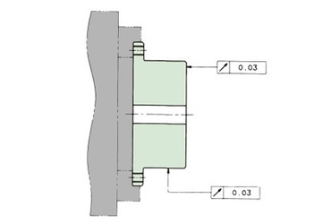
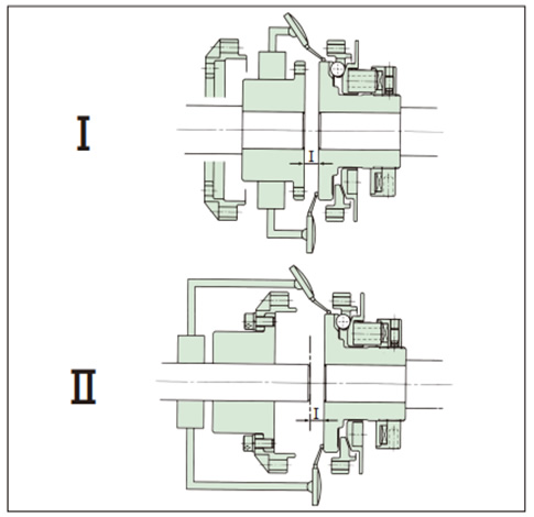
2. Centering method
- (1) Centering Method I
- a. Separate the flange from the boss and center flange.
- b. Move it. Measure the dimension I (Table 1).
- c. Fix a dial gauge on the shaft and measure the runout on the side and outer circumference of the hub.
- (2) Centering Method II
- a. Separate the flange and center flange.
- b. Fix a dial gauge on the shaft and measure the runout on the side and outer circumference of the hub.
- c. Move the boss. Measure the dimension I. (Table 1)
| Note | Be sure to install according to the I dimension in Table 1. It may not be possible to use it without backlash. |
Table 1
| Model number | I Dimensions mm |
|---|---|
| TGX10-C | 2 |
| TGX20-C | 3 |
| TGX35-C | 3 |
| TGX50-C | 4 |
| TGX70-C | 4 |
Allowable misalignment amount
| Model number | Allowable misalignment | ||
|---|---|---|---|
| Declination angle deg. | Eccentricity mm | End play mm | |
| TGX10-C | 0.6 | 0.1 | ±0.5 |
| TGX20-C | 0.6 | 0.1 | ±0.5 |
| TGX35-C | 0.6 | 0.1 | ±0.5 |
| TGX50-C | 0.6 | 0.1 | ±0.6 |
| TGX70-C | 0.6 | 0.1 | ±0.7 |
Reference Angular Misalignment θ = Hub side runout value per 0.1°
| Model number | Outer diameter mm | Hub runout value mm |
|---|---|---|
| TGX10-C | Φ53 | 0.092 |
| TGX20-C | Φ75 | 0.131 |
| TGX35-C | Φ98 | 0.171 |
| TGX50-C | Φ138 | 0.241 |
| TGX70-C | Φ177 | 0.309 |
*Please install so that Angular Misalignment is as small as possible.
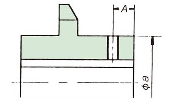
3. Shaft hole processing
Please refer to Instruction Manuals for disassembly, processing, and assembly when processing the shaft hole of Shock Guard TGX and Coupling Type TGX-C.
| Model number | size | |||||
|---|---|---|---|---|---|---|
| A x screw diameter | B x screw diameter | C x screw diameter | a mm | b mm | c mm | |
| TGX10 | 21×M4 or less | - | - | 30 | - | - |
| TGX20 | 20.5 x M5 or less | - | - | 40 | - | - |
| TGX35 | 20.5×M6 | - | - | 55 | - | - |
| TGX50 | 24.5×M6 | - | - | 80 | - | - |
| TGX70 | 25×M6 | - | - | 100 | - | - |
| TGX10-C | - | 8 x M4 or less | 21×M4 or less | - | 33 | 30 |
| TGX20-C | - | 12 x M8 or less | 20.5×M5 | - | 55 | 40 |
| TGX35-C | - | 11 x M10 or less | 20.5×M6 | - | 70 | 55 |
| TGX50-C | - | 13 x M10 or less | 24.5×M6 | - | 92 | 80 |
| TGX70-C | - | 15 x M10 or less | 25×M6 | - | 116 | 100 |
Shock Guard

Coupling Type
Chuck hub end face and center it as shown in the diagram below before machining.
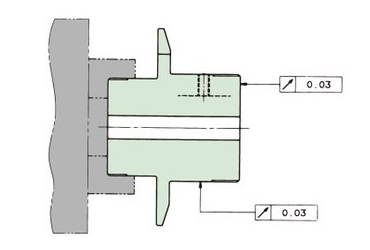
Chuck the flange outer diameter and perform centering as shown in the diagram below before machining.