technical data Mechanical protector
Shock Guard TGM
Torque Settings
By simply turning the adjustment screw with a hex wrench, you can easily set the trip torque with high precision.
- 1. The minimum torque is temporarily set at the time of shipment. The top of the adjustment screw is aligned with the minimum torque (torque scale 1) on the nameplate. This is the reference tightening amount.
- 2. Before setting the torque, apply Loctite 243 or an equivalent product to the exposed threads of the adjusting screw. This will prevent loosening after the torque is set.
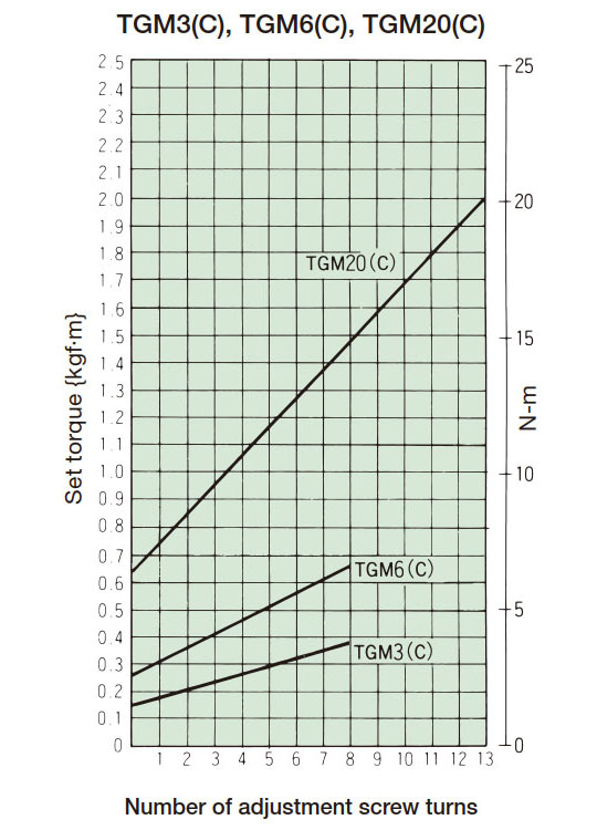
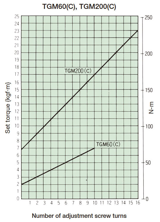
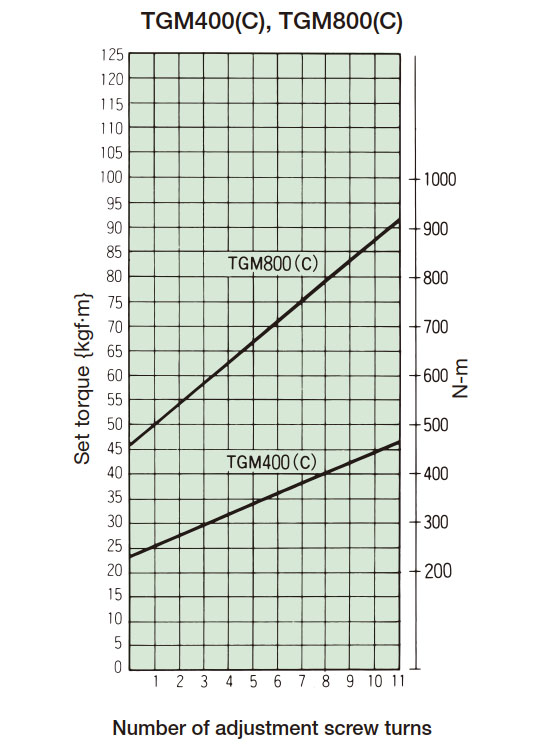
- 3. Read the tightening amount-torque correlation diagram or the table on the right to determine the tightening angle of the adjusting nut that corresponds to the predetermined trip torque, and then tighten it. Initially, set it about 60° before the tightening value read from the correlation diagram, then attach it to the machine and perform a trip test, gradually tightening it to set it to the optimum trip torque. The trip torque of the product will not necessarily match the tightening amount-torque correlation diagram below, so use it as a guide only.
- 4. Do not set the torque lower than the minimum torque (torque scale 1 on the nameplate). If a trip torque lower than the minimum torque is required, use a weak spring.
- 5. Do not turn the adjusting screw when in tripped state.
- 6. If you specify a torque setting, we can set the torque at the factory before shipping. (Please refer to Instruction Manuals.)
| Model number | Torque change per rotation N・m{kgf・m} |
Total rotation speed |
|---|---|---|
| TGM3 | 0.28 {0.029} | 8 |
| TGM6 | 0.48 {0.049} | 8 |
| TGM20 | 1.02 {0.10} | 13 |
| TGM60 | 4.90 {0.5} | 10 |
| TGM200 | 9.80 {1.0} | 16 |
| TGM400 | 20.6 {2.1} | 11 |
| TGM800 | 41.2 {4.2} | 11 |
Set torque = min. torque + (torque change per rotation x number of rotations of the adjusting screw)
Tightening amount-torque correlation diagram
Overload Detection
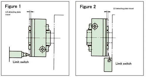
Overload detection can be easily achieved with limit switches.
When Shock Guard trips due to an overload, the cam follower and pocket disengage, causing the camshaft and main body (case) to spin freely.
Accordingly, the LS detection plate on the side of the case slides in the axial direction.
This movement can be detected by a limit switch and can turn off the power or sound an alarm.
This detection is possible regardless of whether the camshaft side or the main body (case) side is stopped.
The LS detection plate slides three times per trip.
- (1) Table 1 shows the travel distance and force required for the LS detection plate. Use this table to select an appropriate limit switch that satisfies PT (travel until operation) and OF (force required for operation).
- (2) Figures 1 and 2 show examples of limit switch installation.
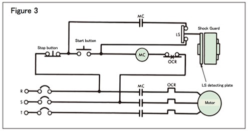
- (3) Connect the b contact of the limit switch in parallel with the contact of the start button.
- (4) A typical circuit example is shown in Figure 3. A circuit incorporating a self-holding circuit is recommended.
| Model number | Travel amount mm | Movement force N{gf} |
|---|---|---|
| TGM3 | 4 | 3.9 {400} |
| TGM6 | 4 | 3.9 {400} |
| TGM20 | 4 | 3.9 {400} |
| TGM60 | 6 | 3.9 {400} |
| TGM200 | 6 | 5.4 {550} |
| TGM400 | 8 | 5.9 {600} |
| TGM800 | 8 | 5.9 {600} |
・Limit switch installation example
・Circuit example
Installation
1. Mounting to the shaft
- - We recommend a shaft diameter tolerance of h7 when attaching Shock Guard to the shaft. Please use a JIS 1301-1996 (New JIS Standard) parallel key.
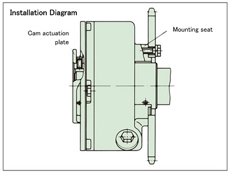
When installing the key, be careful not to touch the top of the key. - - To secure the cam to the shaft, use the three set bolts on the cam operating plate (one for the key, two for the shaft).
- - When attaching Shock Guard to the end of a shaft, etc., if the set bolt on the cam operating plate cannot be used due to the fitting relationship, please use the tap on the mounting seat side.
This tap does not come with a set bolt, so please prepare one with the appropriate length for the shaft hole diameter.
Make sure the head of the set bolt does not protrude from the outer circumference of the camshaft. If the head is left protruding, it may interfere with the inner diameter or side of the mounting seat when Shock Guard trips. - - If there is a risk that the set bolt may loosen due to vibrations during operation, apply Loctite 243 or an equivalent product to prevent loosening.
2. Installing the drive member
- - When installing drive members such as sprockets, pulleys, gears, and couplings, use the three mounting seats and fasten with the tightening torque shown in Table 2.
- ・Please refer to Instruction Manuals when installing the sprocket. Please contact us if you plan to use it in combination with Power-Lock (fastening element) or a non-backlash coupling.
3. Mounting bolts
The recommended screw-in length and tightening torque for the bolts attached to the case seat are shown in Table 2.
Also, the bolt pilot bore of the attachment should be JIS B10012 class or below.
| Model number | Bolt screw length mm | Bolt tightening torque N・m{kgf・m} | Screw pilot pilot bore of attachment (mm) |
|---|---|---|---|
| TGM3 | 6~7 | 2.0~2.9 {0.2~0.3} | 4.5 |
| TGM6 | 6~7 | 2.0~2.9 {0.2~0.3} | 4.5 |
| TGM20 | 8~9 | 3.9~5.9 {0.4~0.6} | 5.5 |
| TGM60 | 9~11 | 6.9~11 {0.7~1.1} | 6.6 |
| TGM200 | 15~17 | 34~51 {3.5~5.2} | 11.0 |
| TGM400 | 18~25 | 59~89 {6.0~9.1} | 14.0 |
| TGM800 | 18~25 | 59~89 {6.0~9.1} | 14.0 |
4. Consolidation
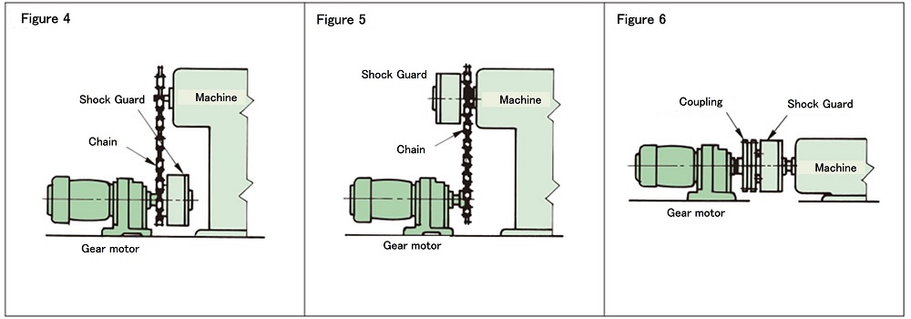
Input and output connections are made between variable speed reducers, intermittent drive devices, etc. and the other machine or device.
Figures 4, 5, and 6 show typical connection examples.
Resurrection
Since it is Auto reset system, it will automatically reset just by restarting the drive side such as the motor.
- 1. If Shock Guard trips due to an overload, stop the rotation and remove the cause of the overload.
- 2. When resetting, reset (re-engage) by reducing the input rotation speed to 50 r/min or lower or by inching the motor.
Do not reset Shock Guard by turning the body or shaft by hand. - 3. You will hear a "click" when the cam follower fits into the pocket.
Lubrication
High-quality grease is packed into the product before shipping, so it can be used as is. No greasing is required under normal use.
| EXXON MOBILE | Mobilux EP-2 |
|---|
*The product names listed in the table above are trademarks of ExxonMobil Japan LLC.

