technical data Mechanical protector
Shock Guard TGB Handling
1. Trip torque setting
- (1) When shipping, all Shock Guard TGBs are set to the minimum torque point. Make sure the indicator points to zero on the torque scale.
(Please refer to the diagram for each size.) - (2) For TGB70 to 130, loosen the hex nuts that prevent the adjustment bolts from loosening in three places. (For TGB08 to 50, you can turn the adjustment nuts as they are.)
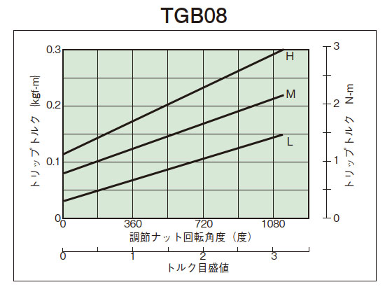
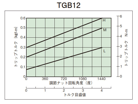
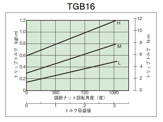
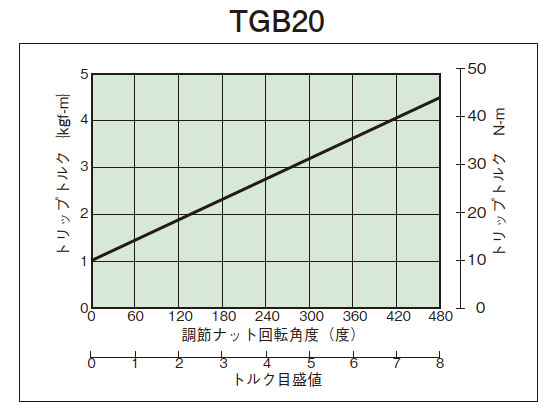
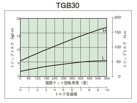
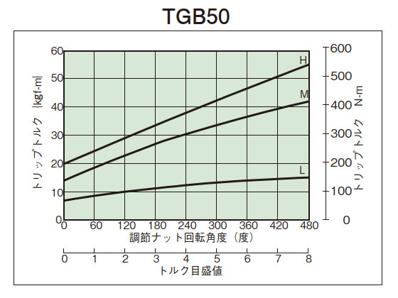
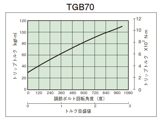
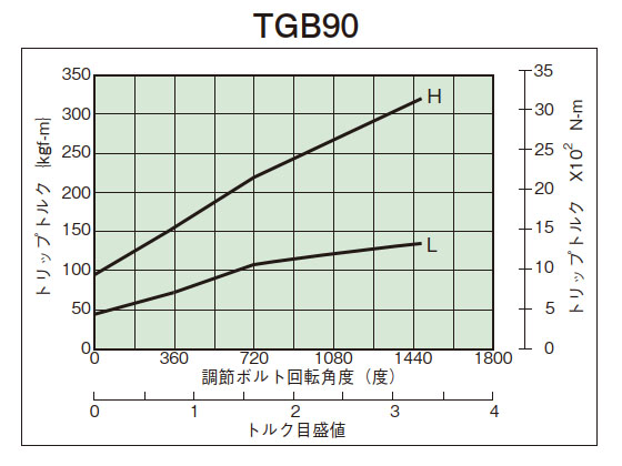
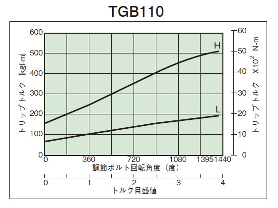
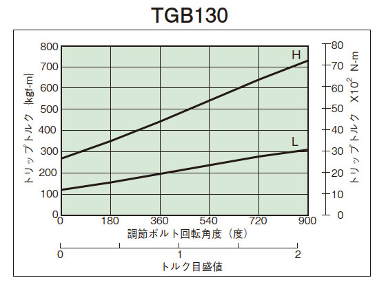
- (3) From the tightening amount-torque correlation diagram (below), read the tightening angle of the adjustment nut (bolt) that corresponds to the predetermined trip torque, and then tighten it. Initially, set it about 60° in front of the tightening value read from the correlation diagram, then attach it to the machine and perform a trip test, gradually tightening it until you reach the optimum trip torque. The trip torque of the product will not necessarily match the tightening amount-torque correlation diagram below, so please use it as a guide.
- (4) For TGB20 to 50, tighten one lock screw to prevent loosening of the adjustment nut. For TGB70 to 130, tighten the hexagon nut to prevent loosening.
(The adjustment nuts of TGB08 to 16 are coated to prevent loosening.) - (5) Do not turn the adjusting nut (bolt) beyond the maximum torque scale value. When tripping occurs, the disc spring will no longer have room for deflection and will be locked. (TGB08 to 16 use a coil spring.)
2. Tightening amount-torque correlation diagram
3. Shaft hole processing
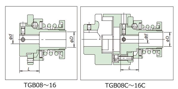
TGB08~16
· The boss is made of iron-based sintered alloy and has been surface hardened.
- (1) Loosen the adjusting nut and disassemble all parts. At this time, be careful not to get any dust or dirt on the parts.
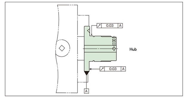
- (2) Chuck the outer diameter of the boss flange and center it at the boss. The boss is made of sintered iron alloy with a hardened surface, so we recommend using a carbide cutting tool (JIS symbol 9-20, K-01).
- (3) The keyway should be machined directly below the tap for the set screw.
- (4) When reassembling after machining the shaft bore, apply lubricating grease to the drive ball and thrust bearing.
- (5) When machining the shaft hole, refer to the table and diagram below and perform stepped machining.

| Model number | Shaft Hole Diameter Φd mm |
Shaft hole processing length L mm |
Counterbore diameter ΦD mm |
|---|---|---|---|
| TGB08 TGB08-C |
Φ6 or more Φ8 or less | 20 | Φ11 |
| TGB12 TGB12-C |
Φ7 or more and less than Φ10 | 20 | Φ15 |
| Φ10 or more and less than Φ12 | 30 | ||
| Φ12 | full length | Unnecessary | |
| TGB16 TGB16-C |
Φ8 or more and less than Φ10 | 20 | Φ15 |
| Φ10 or more and less than Φ12 | 30 | ||
| Φ12 or more Φ16 or less | full length | Unnecessary |
TGB20~130
- The boss has been subjected to thermal treatment.
- (1) Loosen the adjusting nut and disassemble all parts.
Remove the shaft retainer and center plate. At this time, be careful not to get any dust or dirt on the parts. - (2) Chuck the outer diameter of the flange of the boss and center it at the boss.
- (3) Tap the set screw in two places: on the keyway and at a 90° angle.
- (4) When reassembling after machining the shaft bore, apply lubricating grease to the drive ball and thrust bearing.
4. Reinstatement
Since it is Auto reset system, it will automatically reset just by restarting the drive side such as the motor.
- (1) If the Shock Guard trips due to an overload, stop the rotation and remove the cause of the overload.
- (2) When resetting, reset (re-engage) the gears by setting the input rotation speed to 50 r/min or less or by inching the motor.
⚠Please avoid resetting the Shock Guard by turning the body or shaft by hand as this is dangerous.
- (3) When the drive ball lands in the pocket, you will hear a "click."

