technical data Mechanical protector
Torque Keeper TFK handling
Handling 1
- 1. All Torque Keeper are shipped with pilot bore. Please drill the boss shaft hole after disassembly. For details on drilling the shaft hole, please see here.
- 2. When disassembling two or more Torque Keeper, be careful not to interchange parts. When reassembling, be sure to use the same parts as when shipped. If parts are interchanged, the torque curve provided will not match the actual slip torque.
- 3. When using toothed belts, roller chains, etc. for winding transmissions, be careful not to tension them too much. Excessive tension may prevent stable slip torque from being obtained.
Handling 2
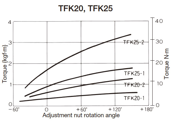
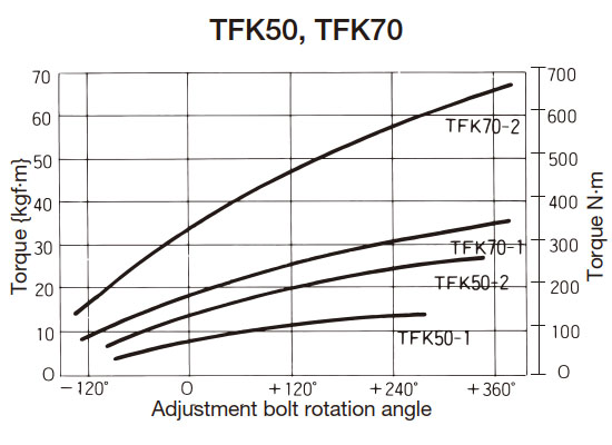
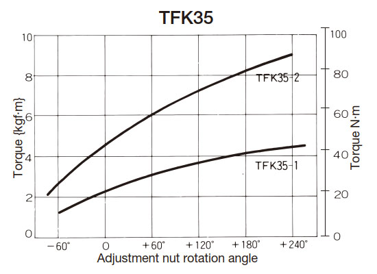
For each model number of Torque Keeper, the torque is set to a maximum of 50% of the set torque range (see product page), and the torque curve is attached when shipped.
This 50% torque is called the 0 point, and slip torque is set based on this 0 point.
To set the slip torque for TFK20, 25, and 35, tighten the adjustment nut with a commercially available hook wrench. To set the slip torque for TFK50 and 70, tighten the three adjustment bolts with a commercially available wrench. See below for how to recreate the 0 point.
Slip torque setting
TFK20・25・35
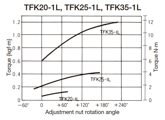
- (1) When the required slip torque is above the 0 point, tighten the adjustment nut by the required angle according to the torque curve attached to the main unit. Tightening the adjustment nut can be done easily using the torque scale (angle display) and match marks.
- (2) If the required slip torque is below the 0 point, loosen the adjustment nut beyond the required angle according to the torque curve attached to the main unit, and then tighten it to the required angle.
(Example) When setting the slip torque from 0 point to -30°.
- 1. Loosen the adjustment nut from the 0 point to -60°.
- 2. Tighten the adjustment nut from -60° to -30°.
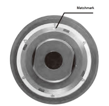
TFK20, 25, 35 torque scale
TFK50・70
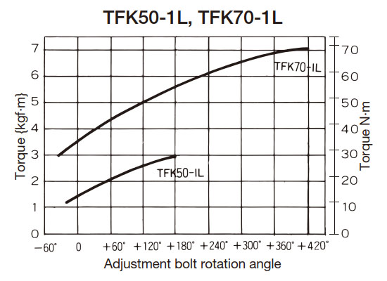
- (1) When the required slip torque is above the 0 point, retighten the three adjustment bolts by the required angle according to the torque curve attached to the main unit. Tightening the adjustment bolts can be easily done using the torque scale (angle display) and match marks.
- (2) If the required slip torque is below the 0 point, loosen the three adjustment bolts beyond the required angle according to the torque curve attached to the main unit, and then tighten them to the required angle.
(Example) When setting the slip torque from 0 point to -60°.
- 1. Loosen the adjustment bolt from the 0 point to -90°.
- 2. Tighten the adjustment bolt from -90° to -60°.
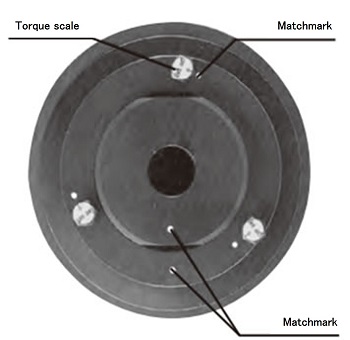
TFK50/70 torque scale
(Note) When initially setting up Torque Keeper or when changing the slip torque setting during use, we recommend running the unit for 2 to 3 minutes before starting actual operation to obtain a more stable slip torque. Run-in should be performed as follows, depending on the slip torque to be set:
(1) When used at slip torque below 0 point.
- 1. Run the engine at 0 point torque for 2 to 3 minutes.
- 2. Set the slip torque as described above before starting operation.
(2) When used at a slip torque above the 0 point.
- 1. Set the slip torque as described above.
- 2. Run the engine for 2 to 3 minutes.
- 3. Return the adjustment nut or adjustment bolt to the 0 point.
- 4. Set the slip torque again before starting normal operation.
Torque curve (common to coupling types)
Weak spring specification
Standard spring specifications { } are reference values.
How to recreate 0 points
When reassembling after machining the shaft hole, please follow the steps below.
TFK20・25・35
- 1. When reassembling, align the torque scale 0 with the position of the boss's set screw (product number (8)). (Be careful not to reverse it 180 degrees.)
- 2. Tighten the adjusting nut by hand, then use the hook wrench to tighten it further until the match mark on the adjusting nut is at the 0 position on the torque scale.
TFK50・70
- 1. Tighten the adjustment nut and align the alignment marks on the adjustment nut and boss.
- 2. Tighten the adjustment bolt by hand, then use a wrench or adjustable wrench to tighten it further until the 0 on the torque scale matches the match mark.
- Notes: 1. The torque curve scale 0 indicates 50% of the maximum torque.
- Note 2: Each torque curve is a representative example. For actual use, please refer to the torque curve included with the unit.

