technical data Mechanical protector TG Sensor - Handling and Wiring
Do not swing it around, pull it with excessive force, or hit the detection part with any objects.
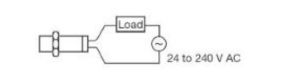
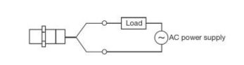
AC type TGS8
Circuit diagram
- The polarity (brown/blue) of the TG sensor does not need to be considered.
Wiring precautions
- Always connect the load before turning on the power.
Please note that powering on the device without connecting a load will cause damage.
- When power lines or motor lines pass near the TG sensor cord, the TG sensor cord should be routed in a separate conduit to eliminate the effects of surges and noise.
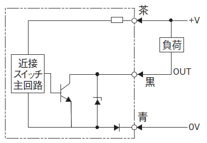
DC type TGS8DN
Circuit diagram
Wiring Information (AC Type TGS8)
- Power connection
Always connect through a load. Direct connection will damage the internal components.
• Implementation of metal piping
When power lines or motor lines pass near the cords of proximity switches, separate metal conduits should be used to prevent malfunctions and damage.
Surge protection
If there are devices that generate large surges (motors, welding machines, etc.) near where the TG sensor is used, the TG sensor also has a built-in surge absorption circuit,
Please ensure that surge absorbers, such as baristors, are inserted at the source of the surge.
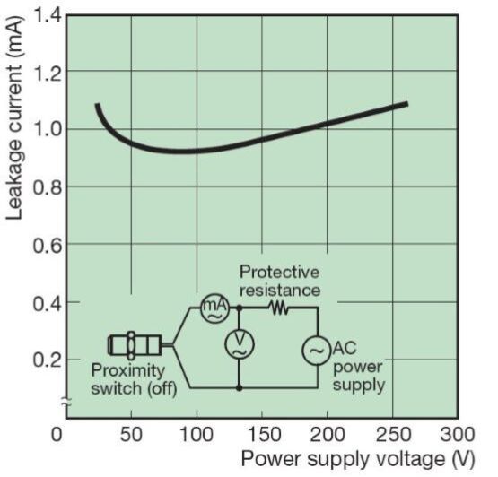
- Effects of consumption (leakage) current
Even when the TG sensor is OFF, a small amount of current flows as current consumption to keep the circuit running. (See graph "Current Consumption (Leakage) Characteristics")
This may cause a small voltage to be generated across the load, potentially leading to a failure to reset the load. Please ensure that this voltage is below the load's reset voltage before use.
Also, when using a relay as a load, please note that depending on the relay's structure, leakage current may cause a humming noise when it is turned OFF.
• Current consumption (leakage) characteristics
- When the power supply voltage is low
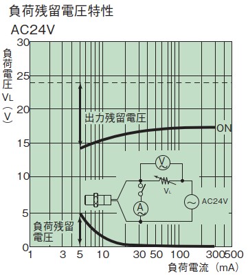
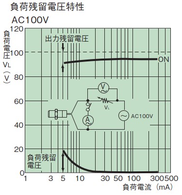
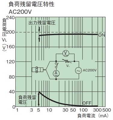
When the power supply voltage is less than AC48V and the load current is 10mA or less, the output residual voltage when the TG sensor is ON is large.
Furthermore, the residual voltage of the load increases when the system is turned off. (See graph "Load Residual Voltage Characteristics")
- When the load current is small
When the load current is less than 5mA, the residual voltage of the load on the TG sensor increases. (See graph "Load Residual Voltage Characteristics")
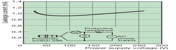
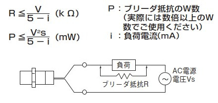
In such cases, connect a bleeder resistor in parallel with the load as shown in the diagram below, and ensure that a load voltage of 5mA or more flows through it, so that the residual voltage is less than or equal to the load's recovery voltage.
The bleeder resistance value and allowable power should be calculated using the following formula. However, to allow for a margin, use 20kΩ and 1.5W (3W) or more when using AC100V.
For AC200V, we recommend using a 39kΩ resistor with 3W (5W) or higher. (If heat generation is a concern, please use a resistor with a wattage equal to or greater than the one indicated in parentheses.)
Load residual voltage characteristics
Regarding loads with large inrush currents
Large loads with high inrush current (1.8A or more), such as lamps and motors, can degrade or damage the switching elements.
In such cases, please use a relay.

