Technical data Coupling Handling
ECHT-FLEX Coupling NEF/NEH Series
Centering
(1) Single type, spacer type
The higher the initial centering accuracy of the coupling, the less eccentric rotational stress that occurs during use.
Changes during use due to bearing wear, settlement of the installation surface, temperature changes, vibrations, etc. will shorten the life of your equipment and couplings.
Please adjust it periodically according to the following procedure.
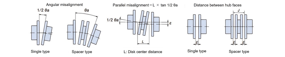
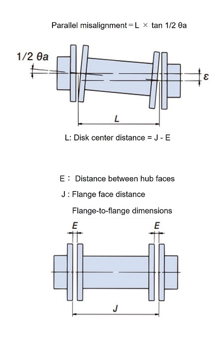
Eccentricity (parallelism error) = L×tan 1/2 θa L: Distance between disk centers = J - E
Please note that the single type cannot absorb eccentricity (misalignment of the shaft center).
The coupling's allowable angular misalignment (Angular Misalignment), eccentricity (parallel error), and flange face dimensional error are correlated, and as one increases the other decreases, they must be considered simultaneously. Be sure to perform initial centering to within the recommended values below.
| Model number | Declination angle (Angular Misalignment) | eccentricity (parallel error) ε [mm] |
Hub face to face Dimensional error E [mm] |
|
|---|---|---|---|---|
| 1/2 θ a [deg] |
Dial reading | |||
| NEF02S | 0.25 | 0.25 | *(Note) Cannot be absorbed |
4.9±0.25 |
| NEF04S | 0.25 | 0.29 | 6.1±0.25 | |
| NEF10S | 0.25 | 0.35 | 6.6±0.25 | |
| NEF18S | 0.25 | 0.40 | 8.3±0.25 | |
| NEF25S | 0.25 | 0.45 | 11.2±0.25 | |
| NEF45S | 0.25 | 0.55 | 11.7±0.25 | |
| NEF80S | 0.25 | 0.62 | 11.7±0.25 | |
| NEF130S | 0.25 | 0.73 | 16.8±0.25 | |
| NEF210S | 0.25 | 0.84 | 17.0±0.25 | |
| NEF340S | 0.25 | 0.93 | 21.6±0.25 | |
| NEF540S | 0.25 | 1.07 | 23.9±0.25 | |
| NEF700S | 0.25 | 1.20 | 27.2±0.25 | |
*Note) The single type cannot absorb eccentricity (Angular Misalignment) due to its structure, but when centering, please adjust it to within 0.02 mm.
| Model number | Declination angle (Angular Misalignment) | eccentricity (parallel error) ε [mm] |
Hub face to face Dimensional error E [mm] |
|
|---|---|---|---|---|
| θ a [deg] |
Dial reading TIR [mm] |
|||
| NEF02W | 0.5 | 0.50 | 0.075 | 4.9±0.25 |
| NEF04W | 0.5 | 0.58 | 0.13 | 6.1±0.25 |
| NEF10W | 0.5 | 0.71 | 0.14 | 6.6±0.25 |
| NEF18W | 0.5 | 0.81 | 0.17 | 8.3±0.25 |
| NEF25W | 0.5 | 0.91 | 0.18 | 11.2±0.25 |
| NEF45W | 0.5 | 1.10 | 0.22 | 11.7±0.25 |
| NEF80W | 0.5 | 1.25 | 0.25 | 11.7±0.25 |
| NEF130W | 0.5 | 1.46 | 0.27 | 16.8±0.25 |
| NEF210W | 0.5 | 1.69 | 0.31 | 17.0±0.25 |
| NEF340W | 0.5 | 1.86 | 0.33 | 21.6±0.25 |
| NEF540W | 0.5 | 2.14 | 0.37 | 23.9±0.25 |
| NEF700W | 0.5 | 2.41 | 0.46 | 27.2±0.25 |
| NEH09W | 0.35 | 1.68 | 0.30 | 19.0±0.25 |
| NEH14W | 0.25 | 1.20 | 0.30 | 19.0±0.25 |
| NEH20W | 0.25 | 1.34 | 0.33 | 19.0±0.25 |
| NEH30W | 0.25 | 1.50 | 0.36 | 21.5±0.25 |
| NEH41W | 0.25 | 1.64 | 0.43 | 24.0±0.25 |
| NEH55W | 0.25 | 1.94 | 0.50 | 29.5±0.25 |
| NEH70W | 0.25 | 2.05 | 0.51 | 31.3±0.25 |
| NEH90W | 0.25 | 2.23 | 0.55 | 32.0±0.25 |
| NEH110W | 0.25 | 2.43 | 0.55 | 32.5±0.25 |
| NEH135W | 0.25 | 2.56 | 0.60 | 34.0±0.25 |
| NEH150W | 0.25 | 2.74 | 0.65 | 34.5±0.25 |
| NEH180W | 0.25 | 2.85 | 0.70 | 35.5±0.25 |
(2) Long spacer type
| Model number | Declination angle (Angular Misalignment) | eccentricity (parallel error) ε [mm] |
Hub face to face Dimensional error E [mm] |
|
|---|---|---|---|---|
| θ a [deg] |
Dial reading TIR [mm] |
|||
| NEF04W | 0.5 | 0.58 | L×0.43×10⁻² | 6.1±0.25 |
| NEF10W | 0.5 | 0.71 | L×0.43×10⁻² | 6.6±0.25 |
| NEF18W | 0.5 | 0.81 | L×0.43×10⁻² | 8.3±0.25 |
| NEF25W | 0.5 | 0.91 | L×0.43×10⁻² | 11.2±0.25 |
| NEF45W | 0.5 | 1.10 | L×0.43×10⁻² | 11.7±0.25 |
| NEF80W | 0.5 | 1.25 | L×0.43×10⁻² | 11.7±0.25 |
| NEF130W | 0.5 | 1.46 | L×0.43×10⁻² | 16.8±0.25 |
| NEF210W | 0.5 | 1.69 | L×0.43×10⁻² | 17.0±0.25 |
| NEF340W | 0.5 | 1.86 | L×0.43×10⁻² | 21.6±0.25 |
| NEF540W | 0.5 | 2.14 | L×0.43×10⁻² | 23.9±0.25 |
| NEF700W | 0.5 | 2.41 | L×0.43×10⁻² | 27.2±0.25 |
| NEH09W | 0.35 | 1.68 | L×0.31×10⁻² | 19.0±0.25 |
| NEH14W | 0.25 | 1.20 | L×0.22×10⁻² | 19.0±0.25 |
| NEH20W | 0.25 | 1.34 | L×0.22×10⁻² | 19.0±0.25 |
| NEH30W | 0.25 | 1.50 | L×0.22×10⁻² | 21.5±0.25 |
| NEH41W | 0.25 | 1.64 | L×0.22×10⁻² | 24.0±0.25 |
| NEH55W | 0.25 | 1.94 | L×0.22×10⁻² | 29.5±0.25 |
| NEH70W | 0.25 | 2.05 | L×0.22×10⁻² | 31.3±0.25 |
| NEH90W | 0.25 | 2.23 | L×0.22×10⁻² | 32.0±0.25 |
| NEH110W | 0.25 | 2.43 | L×0.22×10⁻² | 32.5±0.25 |
| NEH135W | 0.25 | 2.56 | L×0.22×10⁻² | 34.0±0.25 |
| NEH150W | 0.25 | 2.74 | L×0.22×10⁻² | 34.5±0.25 |
| NEH180W | 0.25 | 2.85 | L×0.22×10⁻² | 35.5±0.25 |
Relationship between eccentricity (parallelism error) and angular misalignment (Angular Misalignment) of spacer type
Eccentricity (parallel error)
(Eccentricity (parallelism error) per unit length of the center distance L of the discs)
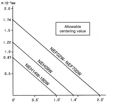
Allowable angle deviation (Angular Misalignment) (θa)
Eccentricity (parallel error)
(Eccentricity (parallelism error) per unit length of the center distance L of the discs)
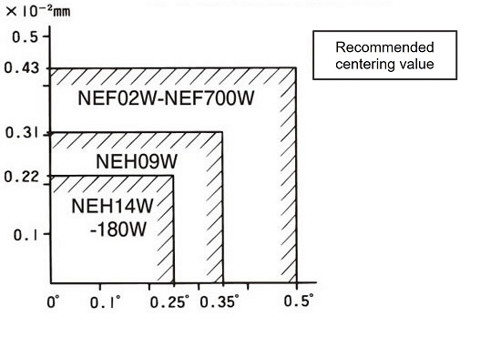
Allowable angle deviation (Angular Misalignment) (θa)
- (1) Adjustment of the hub-to-hub dimension (E)

For both the spacer type and single type, measure the E dimension at four locations every 90 degrees, and adjust the hub position so that the average value is within E±0.25 mm.
If the drive shaft or driven shaft is a stepped shaft, the adjustment margin may be limited, so please make sure that the E dimension can be adjusted in advance.
- (2) Angular Misalignment (θ°)

- (a) Fix the dial gauge to one of the hubs as shown in the figure above, rotate the hub to find the minimum reading on the dial gauge, and set it to zero.
- (b) Rotate the dial hub 360 degrees and read the declination (Angular Misalignment) value.
- (c) Adjust the equipment using shims or other tools so that the reading on the dial gauge falls within the range of the recommended declination (Angular Misalignment) values in the table.
- (3) Adjustment of eccentricity (parallelism error) (ε) mm

- (a) Attach a dial gauge to the hub flange as shown in the diagram above, rotate the hub, find the minimum reading on the dial gauge, and set it to zero.
- (b) Rotate the hub on the fixed side of the dial gauge 360 degrees and read the eccentricity value.
- (c) The dial gauge may show abnormal runout at the outer periphery of the hub at the drilled hole. This is because the flange bulges outward when machining the drilled hole, so be sure to avoid this area when taking the reading.
- (d) Adjust the equipment by moving it using a shim or similar tool so that the reading on the dial gauge is within a range of two times the recommended eccentricity (parallelism error) value (ε) shown in the table.
- (e) If you move the equipment to adjust the eccentricity (parallelism error), please readjust the declination (Angular Misalignment).
- (4) Repeat the above steps until all of the coupling displacements reach the appropriate values.
- (5) Tighten all U-nuts to the specified torque shown in the next section.
Torque transmission in ECHT-FLEX coupling is achieved by the friction force generated between the disc and washer due to the tightening force of the U-nut.
Be sure to observe the tightening torque of the U-nut described in the next section.
1. Reamer bolt tightening torque table
ECHT-FLEX couplings transmit power by the frictional force of the reamer bolt and U-nut.
Be sure to tighten it securely to the specified torque.
| Model number | Reamer bolt tightening torque [N・m] |
Reamer bolt size | |
|---|---|---|---|
| NEF02 | 4.90 | M5 | |
| NEF04 | 8.82 | M6 | |
| NEF10 | 8.82 | M6 | |
| NEF18 | 21.6 | M8 | |
| NEF25 | 21.6 | M8 | |
| NEF45 | 41.2 | M10 | |
| NEF80 | 78.4 | M12 | |
| NEF130 | 78.4 | M12 | |
| NEF210 | 177 | M16 | |
| NEF340 | 177 | M16 | |
| NEF540 | 470 | M20 | |
| NEF700 | 657 | M24 | |
| NEH09 | 470 | M20 | |
| NEH14 | 568 | M22 | |
| NEH20 | 784 | M24 | |
| NEH30 | 1170 | M27 | |
| NEH41 | 1590 | M30 | |
| NEH55 | 2250 | M36 | |
| NEH70 | 2550 | M36 | |
| NEH90 | 3230 | M39 | |
| NEH110 | 3920 | M42 | |
| NEH135 | 4900 | M45 | |
| NEH150 | 5490 | M48 | |
| NEH180 | 6860 | M52 | |
| Model number | Reamer bolt A tightening torque [N・m] |
Reamer Bolt A size |
Reamer bolt B tightening torque [N・m] |
Reamer bolt B size |
||||
|---|---|---|---|---|---|---|---|---|
| NEF45G | 41.2 | M10 | 8.82 | M6 | ||||
| NEF80G | 78.4 | M12 | 21.6 | M8 | ||||
| NEF130G | 78.4 | M12 | 21.6 | M8 | ||||
| NEF210G | 177 | M16 | 41.2 | M10 | ||||
| NEF340G | 177 | M16 | 41.2 | M10 | ||||
| NEF540G | 470 | M20 | 78.4 | M12 | ||||
| NEF700G | 657 | M24 | 78.4 | M12 | ||||
| NEH09G | 470 | M20 | 78.4 | M12 | ||||
| NEH14G | 568 | M22 | 78.4 | M12 | ||||
| NEH20G | 784 | M24 | 177 | M16 | ||||
| NEH30G | 1170 | M27 | 177 | M16 | ||||
| NEH41G | 1590 | M30 | 470 | M20 | ||||
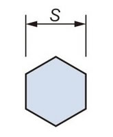
| Size | M5 | M6 | M8 | M10 | M12 | M16 | M20 | M22 | M24 |
|---|---|---|---|---|---|---|---|---|---|
| S | 8 | 10 | 13 | 17 | 19 | 24 | 30 | 32 | 36 |
| Size | M27 | M30 | M36 | M39 | M42 | M45 | M48 | M52 | |
| S | 41 | 46 | 55 | 60 | 65 | 70 | 75 | 80 |
2. Tightening the reamer bolt
When tightening the reamer bolt, if axial force is applied to the coupling hub, the disc may bend and become fixed in that state, so be careful not to apply axial force to the hub when tightening the reamer bolt.
Tighten securely with the tightening torque shown in the table above.
- - The U-nut is made of metal and can be attached and removed up to 20 times. If you need to attach and remove it more than this, please prepare a spare U-nut.
- - There is no need to apply oil or grease to the reamer bolt.
- - The reamer bolt can be inserted from either side.
3. Removing the coupling
When removing a spacer type coupling from the shaft, it can be done without moving the drive or driven machine, which makes centering when re-installing it very easy.
[Removal procedure]
- 1. Loosen all reamer bolts and remove the disc and spacer (Fig. 1).
- 2. Loosen the set bolt that secures the hub, and then slide the hub to remove it (Fig. 2).
- 3. Reassembly is done in reverse order. We recommend checking the centering level after installing both hubs onto the shaft.
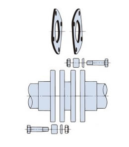
Figure 1
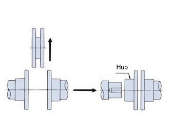
Figure 2
4. Inspection
After one to two hours of actual operation, recheck the angular misalignment and eccentricity (Angular Misalignment error). When doing so, retighten the bolts and nuts to the specified torque in the table above.
Check the reamer bolts and U-nuts every six months to one year to make sure they are not loose. We recommend marking the reamer bolts and U-nuts after installation to check for looseness. Also check for any abnormalities in other parts.

