Technical data Coupling Handling
Jaw-Flex Coupling L Series Handling
Pilot bore product
1. Shaft hole machining, keyway machining
When drilling holes and machining keyways from pilot bore products, please follow the steps below.
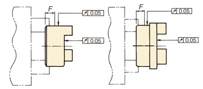
- (1) Chuck the outer diameter of the hub and center it as shown in Figure 1 before machining.
Sintered hub type and plated hubs are made of iron-based sintered alloy and are steam-treated, so we recommend using carbide material (JIS symbol 9-20, K-01) for the cutting tool. (L190 and L225 are made of cast iron.) - (2) The keyway should be machined in a position that avoids the claws. Table 4 shows the recommended tap sizes and positions.
- (3) For shaft bore machining tolerances, we recommend a slip fit fit tolerance as shown in Table 5. Avoid mounting methods that generate internal tensile stress, such as press fit Power-Lock.
Figure 1. Shaft hole machining diagram
| Fit | Fit | Fit | |||
|---|---|---|---|---|---|
| Shaft Tolerance | Hole Tolerance | Shaft Tolerance | Hole Tolerance | Shaft Tolerance | Hole Tolerance |
| h6 h7 |
H7 | j6 j7 |
G7 | k6 k7 |
F7 |
| Sintered hub type, plated finish | Aluminum hub type | |||||||||||||||||||
|---|---|---|---|---|---|---|---|---|---|---|---|---|---|---|---|---|---|---|---|---|
| Size | L035 | L050 | L070 | L075 | L090 | L095 | L099 | L100 | L110 | L150 | L190 | L225 | L050A | L070A | L075A | L090A | L095A | L100A | L110A | |
| L035F | L050F | L070F | L075F | L090F | L095F | L099F | L100F | L110F | L150F | L190F | L225F | |||||||||
| Tap Size | M3 | M4 | M5 | M5 | M6 | M6 | M6 | M6 | M8 | M8 | M8 | M8 | M4 | M5 | M5 | M6 | M6 | M6 | M8 | |
| F(mm) | 3.0 | 8.00 | 9.5 | 10.5 | 10.5 | 12.5 | 13.5 | 12.5 | 20.5 | 17.5 | 25.5 | 25.5 | 8.0 | 9.5 | 10.5 | 10.5 | 10.5 | 17.0 | 20.5 | |
2. Installation
- (1) Fit the hub and key onto both shafts. Do not hammer the hub or key into place. Make sure to properly grind the key.
- (2) Secure the set screws in two places.
- (3) Fit the insert into one side of the hub.
- (4) Assemble both hubs so that the end faces of the claws and the inserts are flush with each other (Fig. 2).
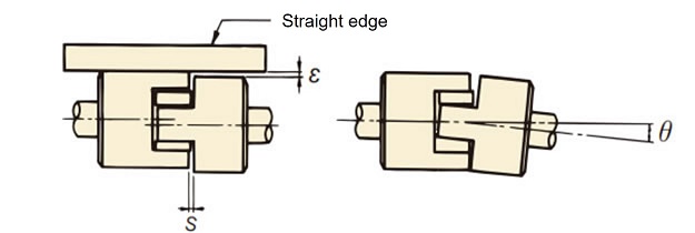
- (5) At this time, correct the misalignment angle (Angular Misalignment) by setting the S dimension (Table 6) so that it is uniform on the circumference as shown in Figure 3. Refer to Table 6 for the allowable misalignment angle (Angular Misalignment) θ.
- (6) Also, place a straight edge on the outer circumference of the hub as shown in Figure 3, and make sure that the ε value in two places approximately 90° apart is equal to or less than the value in Table 6. The life of the insert is greatly affected by the accuracy of centering.
Figure 2
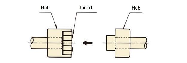
Figure 3. Centering diagram
| Size | Sintered Hub | L035 | L050 | L070 | L075 | L090 | L095 | L099 | L100 | L110 | L150 | L190 | L225 |
|---|---|---|---|---|---|---|---|---|---|---|---|---|---|
| Plating specifications | L035F | L050F | L070F | L075F | L090F | L095F | L099F | L100F | L110F | L150F | L190F | L225F | |
| Aluminum hub | L050A | L070A | L075A | L090A | L095A | L100A | L110A | ||||||
| Allowable eccentricity (parallel error) ε (mm) | 0.38 | 0.38 | 0.38 | 0.38 | 0.38 | 0.38 | 0.38 | 0.38 | 0.38 | 0.38 | 0.38 | 0.38 | |
| Allowable angle deviation (Angular Misalignment) (θ°) | S, M type | 1 | 1 | 1 | 1 | 1 | 1 | 1 | 1 | 1 | 1 | 1 | 1 |
| H type | 0.5 | 0.5 | 0.5 | 0.5 | 0.5 | 0.5 | 0.5 | 0.5 | 0.5 | 0.5 | 0.5 | 0.5 | |
| S(mm) | Standard Dimensions | 0.6 | 1.9 | 1.7 | 1.7 | 1.7 | 1.7 | 1.7 | 1.9 | 2.3 | 2.0 | 2.3 | 2.3 |
| End play (axial displacement) | ±0.3 | ±0.5 | ±0.5 | ±0.5 | ±0.5 | ±0.5 | ±0.5 | ±0.7 | ±0.7 | ±0.7 | ±1.0 | ±1.0 | |
*The aluminum hub type can also be used with M type and H type, but the transmission torque is the same as with the S type.
- (7) If the rotation speed exceeds 2000 r/m, we recommend that the values of ε and θ be half or less of those in Table 6.
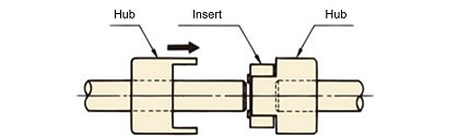
- (8) Another installation procedure is to move both hubs on the shaft so that the end faces of the claws and the end faces of the inserts are flush with each other, as shown in Figure 4. Follow the centering method in the same way as steps (5) and (6). After centering, securely tighten the two set screws with the tightening torque shown in the table on the right (Table 7).
- (9) We recommend using metal adhesive on the set screws to prevent them from loosening.
(Recommended adhesive: Loctite 262)
Figure 4
| Set screw size |
M3 | M4 | M5 | M6 | M8 | M10 | M12 |
|---|---|---|---|---|---|---|---|
| Tightening torque N・m{kgf・m} |
0.78 {0.08} |
1.86 {0.19} |
3.63 {0.37} |
6.66 {0.68} |
16.2 {1.65} |
29.4 {3.0 } |
54.9 {5.6 } |
Finished bore hub
1. Check before installation
- (1) The bore diameter and key type (J: New JIS standard key, E: Old JIS two types) are displayed on the actual hub, so please check the bore diameter and key type for the size you are ordering.
- (2) Two set screws are included.
- (3) Shaft hole diameters of Φ11 or less do not have a keyway and are attached using two set screws.
- (4) Make sure that the tolerance of the shaft diameter to which the hub is attached is in accordance with the recommended tolerances in Table 8.
| Fit | Fit | Fit | |||
|---|---|---|---|---|---|
| Shaft Tolerance | Hole Tolerance | Shaft Tolerance | Hole Tolerance | Shaft Tolerance | Hole Tolerance |
| h6 h7 |
H7 | j6 j7 |
G7 | k6 k7 |
+ 0.040 + 0.015 |
2. Installation
See the section above on installing pilot bore items.
3. Usage environment
- - Use in a well-ventilated area with as little dust and humidity as possible.
- - Avoid using in places where corrosive liquids or gases are present, or in places where there are flammable or explosive substances.
- -Please avoid using outdoors.
4. Inspection
After 1-2 hours of actual operation, recheck the declination (Angular Misalignment) and eccentricity (parallel error).
Also, check for abnormalities in parts and wear of inserts periodically (for example, every six months to one year).
Inserts are consumables and should be replaced regularly.

