technical data Coupling Selection and Procedure
If you would like to see the selection procedures and important points, please proceed below.
If you would like to narrow down or tentatively select a product series,
Please click here.
If your usage conditions have been decided and you would like a detailed selection,
Please click here.
ECHT-FLEX Coupling NEF/NEH Series Selection
1. Calculation of correction torque
1-1. When connecting with a servo motor or stepping motor
The maximum torque of a servo motor or stepping motor is multiplied by Service factor (SF) in the table below according to the type of load to obtain the compensation torque.
| Load Type | Uniform Load | Moderately fluctuating load | Extremely fluctuating load |
|---|---|---|---|
| Service factor (SF) | 1.2 | 1.4 | 1.5 |
1-2. When connecting with a general-purpose motor, etc.
The load torque calculated using the formula below is multiplied by Service factor (SF) in the table on the right according to the type of load to calculate the correction torque.
T = 9550 × P n
- T' = T × SF
- T = Load torque N・m
- P = transmitted power kW
- n = rotational speed r/min
- T' = Corrected torque N・m
| Load Type | Type of engine | ||||
|---|---|---|---|---|---|
| General-purpose electric motors, gas turbines | engine | ||||
| When the moment of inertia is small |
When the moment of inertia is large |
4-cylinder | 6-cylinder | 8-cylinder | |
| Uniform Load | 1.5~1.75 | 1.75~2.0 | 2.5~4.0 | 2.0~2.5 | 1.5~2.0 |
| Moderately fluctuating load | 2.0~2.5 | 2.5~3.0 | 4.0~5.0 | 2.5~3.5 | 2.0~3.0 |
| Extremely fluctuating load | 3.0~4.5 | 4.5~6.0 | 4.5~5.5 | 3.0~4.0 | 2.5~3.5 |
- *If an impact load is applied, multiply the maximum torque that the motor can produce by an impact coefficient of 1 to 2.5 to obtain the corrected torque.
- * When using a clamp or Power-Lock for shaft fastening, make sure that no torque, including the starting torque, is applied that exceeds the friction transmission torque of the shaft hole (see each product page) even momentarily.
2. Shaft diameter
Make sure that the mounting shaft is within the range of shaft diameters that can be mounted on the coupling.
If Power-Lock are included, please also check the size, number and transmission torque of Power-Lock.
For clamp types, make sure that the compensation torque calculated in step 1 is within the transmission torque of the clamp.
If you are installing it on a hollow shaft, you will need to check the strength, so please contact us.
3.Model selection
Please select ECHT-FLEX coupling that satisfies items 1 and 2 above from kW ratings table.
Note: Rotation limit of long spacer type
When using a long spacer type at high speed, the rotation speed must be checked to avoid resonance points.
When selecting a long spacer type, check that the J dimension and rotation speed for each model number are within the limits.
If the rotational speed exceeds the specified value, a higher model number must be selected.
| Model number | Operating speed [r/min] | ||||||||||||||
|---|---|---|---|---|---|---|---|---|---|---|---|---|---|---|---|
| 3600 | 2000 | 1800 | 1500 | 1200 | 1000 | 900 | 750 | 720 | 600 | 500 | 400 | 300 | 200 | 150 | |
| NEF04W | 980 | 1310 | 1380 | 1510 | 1680 | 1840 | 1940 | 2130 | 2170 | 2380 | 2610 | 2910 | 3360 | 4120 | 4750 |
| NEF10W | 1120 | 1500 | 1580 | 1730 | 1940 | 2120 | 2230 | 2450 | 2500 | 2730 | 2990 | 3350 | 3860 | 4730 | 5460 |
| NEF18W | 1180 | 1580 | 1660 | 1820 | 2040 | 2230 | 2350 | 2570 | 2620 | 2870 | 3150 | 3520 | 4060 | 4970 | 5740 |
| NEF25W | 1310 | 1760 | 1850 | 2030 | 2260 | 2480 | 2610 | 2860 | 2920 | 3190 | 3500 | 3910 | 4510 | 5520 | |
| NEF45W | 1440 | 1930 | 2030 | 2230 | 2490 | 2720 | 2870 | 3140 | 3210 | 3510 | 3840 | 4290 | 4960 | ||
| NEF80W | 1560 | 2090 | 2200 | 2410 | 2690 | 2950 | 3100 | 3400 | 3470 | 3800 | 4160 | 4650 | 5360 | ||
| NEF130W | 1780 | 3280 | 2510 | 2750 | 3070 | 3360 | 3540 | 3870 | 3950 | 4330 | 4740 | 5290 | |||
| NEF210W | 1890 | 2520 | 2660 | 2910 | 3250 | 3560 | 3750 | 4100 | 4190 | 4580 | 5020 | 5610 | |||
| NEF340W | 2024 | 2720 | 2870 | 3130 | 3500 | 3830 | 4040 | 4420 | 4510 | 4930 | 5400 | ||||
| NEF540W | 2180 | 2910 | 3070 | 3360 | 3750 | 4100 | 4320 | 4730 | 4820 | 5280 | 5780 | ||||
| NEF700W | 2270 | 3030 | 3190 | 3490 | 3890 | 4260 | 4490 | 4910 | 5010 | 5490 | |||||
| NEH09W | 2190 | 2930 | 3090 | 3380 | 3780 | 4130 | 4360 | 4770 | 4870 | 5330 | 5830 | ||||
| NEH14W | 2190 | 2930 | 3090 | 3380 | 3780 | 4130 | 4360 | 4770 | 4870 | 5330 | 5830 | ||||
| NEH20W | 2400 | 3200 | 3380 | 3690 | 4130 | 4520 | 4760 | 5210 | 5320 | 5820 | |||||
| NEH30W | 2570 | 3430 | 3610 | 3960 | 4420 | 4840 | 5100 | 5580 | 5690 | ||||||
| NEH41W | 2650 | 3540 | 3730 | 4080 | 4560 | 4990 | 5260 | 5760 | 5870 | ||||||
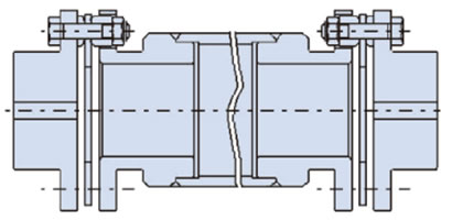
Long spacer high speed specification
One way to avoid the dangerous rotational range is to increase the size of the coupling, but if this is not possible, we can manufacture a product with an increased spacer mass as shown in the diagram on the right.
Points to note when driving servo motors
In a Ball screw drive system using a servo motor, due to the characteristics of the servo motor, oscillation can be amplified depending on the natural frequency of the entire Ball screw drive system and the electrical control status, resulting in large vibrations and abnormal noise.
In such cases, you can avoid this by adjusting the torsional rigidity and moment of inertia of the entire drive system to increase the torsional natural frequency of the mechanical system, or by adjusting the servo gain using the servo motor's electrical control tuning function.
Dynamic Balance Adjustment
ECHT-FLEX couplings have a well-balanced design and do not normally require special balancing, but balancing is necessary when used at high speeds or with long spacers. In such cases, please let us know the rotational speed, JIS balance class, J dimension, or spacer length and we will perform balancing.
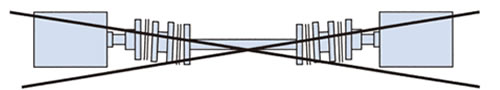
We use two methods for dynamic balancing: (1) drilling holes in the flange end face of the spacer, and (2) attaching balance weights to the outer periphery of the spacer pipe. (When balance weights are attached, the spacer will look like the image below. The attachment position and number of balance weights will vary depending on the conditions.)
Also, please be careful not to interfere with the balance weight while rotating.
If you would like to specify a balancing method for either (1) or (2) above, please let us know when placing your order.
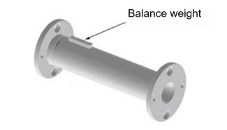
Balance weight installation image
Precautions when the shaft distance is long
If the shaft distance is long, we offer a long spacer type that does not require an intermediate shaft bearing and allows the spacer part to be used in a floating state.

Long spacer type
If you choose to use an intermediate shaft instead of a long spacer for your own convenience, please secure the intermediate shaft with a bearing, etc., to avoid the rope skipping phenomenon. In this case, we recommend using a spacer type disc coupling.
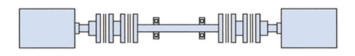
Spacer type + fixed intermediate shaft + spacer type
If the shaft distance is short and the intermediate shaft is used in a floating state, be sure to use the single type.
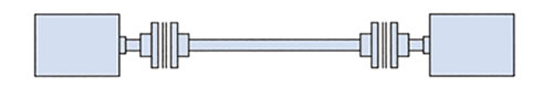
Single type + floating intermediate shaft + single type
Using the spacer type can cause significant rope skipping, which is extremely dangerous and should be avoided at all costs.
Spacer type + floating intermediate shaft + spacer type
Please be especially careful when replacing a gear coupling, Roller chain coupling etc. with a disc coupling.

