technical data Reducer Worm Reducer Handling
This page describes general matters regarding the handling of the EWJ, EWJM(R), EW, EWM(R), SWJ, SWJM(R), SW, SWM(R), and TD series.
For details, please refer to Instruction Manuals attached to the product.
4. Installation
Install the unit in a location with an ambient temperature between 0°C and 40°C, that is well ventilated and has minimal dust and humidity.
Avoid using the product in places where corrosive liquids or gases are present, or in places where there are flammable or explosive substances.
Also, when using outdoors, please use a cover to protect it from direct rain.
- (1) When installing or removing the reducer to or from the driven shaft, be sure to turn off the power to the machine or device before performing the work.
- (2) When attaching or detaching the reducer to or from the driven shaft, be sure to use the hanging bolt on the top of the reducer casing, and never hang wires or the like on the input or output shaft.
- (3) When installing or removing the reducer from the driven shaft, make sure that the reducer is balanced and stable. Working in an unbalanced state will cause the reducer to rotate, which is extremely dangerous. Always ensure that the reducer is stable.
- (4) SWJ25 to 63 and SWJM(R)35 to 63 do not have hanging bolts, so hold the reducer with both hands and insert or remove it from the driven shaft with the output shaft parallel to the driven shaft.
4-1. Solid output shaft type
There are two installation methods for the solid output shaft type: Foot mount (EWJ, EWJM(R), EW, EWM(R), TD-S) and flange mounting (SW, SWM80 to 200).
4-1-1. Foot mount (EWJ, EWJM(R), EW, EWM(R), TD-S)
- - Check that the installation direction is standard.
- If the installation direction is not standard, the oil volume and some lubrication methods will differ, so please refer to the drawing or inquire.
- - The installation reference surface should be smooth and strong enough to avoid any strain, and the installation angle should be within ±1°.
- - Use installation bolts equivalent to JIS strength classification 10.9T.
Recommended installation bolts
EWJ・EWJM size EWJ25 EWJ35 EWJ42 EWJ50 EWJ63 EWJ70 Recommended Bolts M6×15 M8×15 M10×20 M8×25 M10×30 M12×35 EW/EWM size EW80 EW100 EW125 EW150 EW175 EW200 Recommended Bolts M12×40 M14×45 M16×55 M20×60 M20×70 M24×80 TD-S size TD125 TD150 TD175 TD200 TD225 TD250 TD280 TD315 Recommended Bolts M16×55 M20×60 M20×70 M24×80 M24×80 M30×100 M30×100 M30×110 - - Never install in a way that causes deformation of the housing.
- ・The reducer is shipped with lubricating oil sealed inside. The oil filler port is plugged to prevent oil leakage during transport, so please replace the "plug" with the included "pressure vent" before use. If the reducer is operated continuously with the plug in place, the internal pressure may increase, causing oil to leak from the oil seal.
Note) EWJ25-70, EWJM42-70 (including Double reduction) and SWJ25-70, SWJM35-70 do not require a pressure vent, so please use them in the condition they are delivered.
4-1-2. Flange mounting (EWJ25 to 42, EWJM(R)42, SW80 to 200, SWM(R)80 to 200)
The reducer is fixed using the flange surface of the reducer case. Please note the following points.
1. SW/SWM(R) solid output shaft type
- (1) Use the tapped holes on the case flange to secure the reducer, and use the case spigot to position it.
- (2) Adjust the radial runout of the driven shaft, the input/output connection, and the angle, and then install the reducer.
- (3) Please refer to the table below for the recommended bolt sizes for the flange surface. (The bolt size and depth in the table are tap depths.)
Note: If you do not use a case spigot and first connect the input and output, and then fix the flange surface, unexpected loads may be applied to the shaft and bearings, which may shorten the life of the reducer.
Recommended bolt size for flange surface
Reducer size SW80 SW100 SW125 SW150 SW175 SW200 Bolt size M10 depth 20 M10 depth 20 M12 depth 25 M12 depth 25 M14 depth 30 M16 depth 30 Mounting PCD 180 205 255 300 350 380 Number of attachments Distributed equally in 6 locations Distributed equally in 6 locations Distributed equally in 6 locations Equally distributed in 8 locations Equally distributed in 8 locations Equally distributed in 8 locations
2. For EWJ25-42 and EWJM(R)42
When installing the reducer on the floor or wall, please note the following points.
- (1) Use the mounting holes on the flange surface to secure the reducer. The end face of the case protrudes beyond the installation surface of the reducer, so be sure to leave a clearance (ΦD, t) or more between the reducer body and the installation surface as shown in the table and diagram below.
- (2) Adjust the radial runout of the driven shaft, the input/output connection, and the angle, and then install the reducer.
- (3) Refer to the table below for the recommended bolt size and pitch for the flange surface of the reducer.
Note: If the input and output are connected first and then the flange surface is fixed, unexpected loads may be applied to the shaft and bearings, which may shorten the life of the reducer.
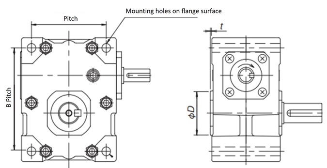
Required clearance from the installation surface
| Size | ΦD | t |
|---|---|---|
| EWJ25 | 46 | 3 |
| EWJ35 | 48 | 1.5 |
| EWJ42 | 63 | 3 |
Mounting bolt size, number, and pitch
| Size | Mounting bolt size | pitch A |
pitch B |
|---|---|---|---|
| EWJ25 | M6 x 60 4 pieces | 57 | 76 |
| EWJ35 | M8 x 80 4 pieces | 71 | 96 |
| EWJ42 | M10 x 90 4 pieces | 88 | 111 |
Recommended tightening torque
| Size | Tightening torque (N・m) |
Tightening torque {kgf・m} |
|---|---|---|
| EWJ25 | 4.9 ~ 5.9 | 0.5 ~ 0.6 |
| EWJ35 | 12 ~ 14 | 1.2 ~ 1.4 |
| EWJ42 | 24 ~ 27 | 2.4 ~ 2.7 |
4-2. Hollow output shaft type
There are three methods for preventing the reducer from rotating: "torque arm mounting," "flange mounting," and "Foot mount (EW-H (hollow output shaft type) only)." We recommend a shaft diameter tolerance of g7 for the driven shaft.
- (1) When inserting the reducer onto the driven shaft, be sure to check that there are no scratches or debris on the outer periphery of the driven shaft or inside the hollow output shaft of the reducer.
- (2) To make insertion easier, apply grease or molybdenum disulfide to the driven shaft.
- (3) If it is difficult to insert, gently tap the end face of the hollow output shaft with a soft hammer to insert it. Be careful not to damage the oil seal.
- (4) The hollow shaft keyway is finished to the new JIS standard. For the key length, please refer to the "Recommended driven shaft length" below.
Recommended driven shaft length (see Figures 1 and 2 below)
| Series | SWJ | SW・EW | SW・EW・TD | TD | ||||||||||||
|---|---|---|---|---|---|---|---|---|---|---|---|---|---|---|---|---|
| Reducer size | 25 | 35 | 42 | 50 | 63 | 70 | 80 | 100 | 125 | 150 | 175 | 200 | 225 | 250 | 280 | 315 |
| Output shaft length: A | 60 | 70 | 80 | 108 | 128 | 130 | 148 | 174 | 200 | 250 | 270 | 290 | 320 | 356 | 404 | 454 |
| Recommended driven shaft length: L | 58 | 68 | 78 | 89 | 109 | 106 | 122 | 146 | 170 | 220 | 238 | 258 | 272 | 303 | 344 | 386 |
4-2-1. Torque arm installation and removal
1. Installation Procedure
Note) Avoid installing a double-shaft input reducer connected with a line shaft.
- (1) Attach the torque arm to the reducer with bolts. Note: If you have purchased a torque arm, use the bolts that come with it. If you are fabricating your own torque arm, use bolts with a strength classification of 10.9 or equivalent.
- (2) Insert the reducer onto the driven shaft.
- (3) Fix the reducer to the driven shaft in the axial direction.
- ・For SWJ25 to 42, we recommend fixing the output shaft end with an end plate as shown in Figure 1.
- ・For SWJ50 to 70, SW80 to 200, EW80-H to 200-H (hollow output type), and TD125H to 315H, we recommend using the retaining ring groove on the hollow output shaft and securing it with a stop ring and end plate as shown in Figure 2. (For detailed dimensions of the hollow output shaft, refer to the product page.)
- (4) After the installation position of the reducer has been determined, fix the torque arm so that the reducer does not rotate together with the driven shaft. At that time, make sure that the torque arm has some freedom in the axial direction.
- Note: Fixing the tip of the torque arm before the reducer may damage the reducer, so please be sure to follow the work procedure carefully. (EW80-H to 200-H are Foot mount. After fixing the output hollow shaft and driven shaft, set the position of the bearing that supports the driven shaft.)
- Note) For the manufacture of end plates, we recommend the dimensions and shapes shown in Table 1 below, which also serve as punched plates.
Figure 1 SWJ25-42
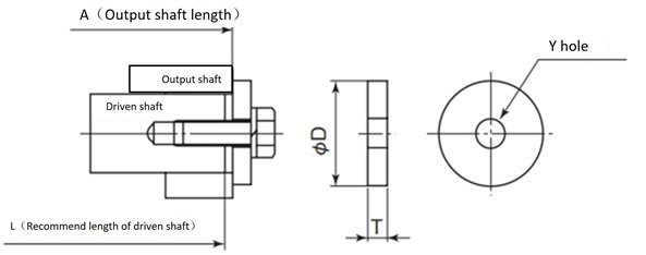
Figure 2 SWJ50-70, SW80-200
EW80-H~200-H・TD125H~315H
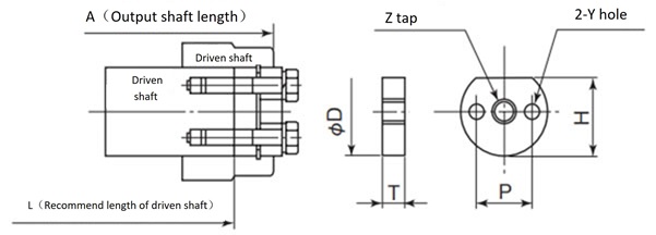
Table 1 Recommended dimensions for end plates (also used as punch plates)
| Size | Output shaft Hole Diameter |
Recommended plate dimensions | Plate bolts (with spring washer) |
Stop ring size |
|||||
|---|---|---|---|---|---|---|---|---|---|
| ΦD | T | H | Z | Y Kiri | P | ||||
| SWJ25 | Φ12 | 16 | 4.5 | - | - | 5.5 | - | 1-M5×15 | - |
| SWJ35 | Φ20 | 26 | 6 | - | - | 9 | - | 1-M8×25 | - |
| SWJ42 | Φ25 | 32 | 6 | - | - | 9 | - | 1-M8×25 | - |
| SWJ50 | Φ30 | 29.6 | 9 | 25 | M12 | - | - | 1-M10×40 | C 30 |
| SWJ63 | Φ35 | 34.6 | 9 | 30 | M12 | - | - | 1-M10×40 | C 35 |
| SWJ70 | Φ40 | 39.6 | 12 | 34 | M12 | 2- 6.6 | 24 | 2-M6×40 | C 40 |
| EW/SW80 | Φ50 | 49.6 | 12 | 44 | M16 | 2- 9 | 30 | 2-M8×45 | C 50 |
| EW/SW100 | Φ55 | 54.6 | 14 | 48 | M16 | 2-11 | 32 | 2-M10×55 | C 55 |
| EW/SW125 | Φ70 | 69.5 | 14 | 62 | M24 | 2-14 | 44 | 2-M12×60 | C 70 |
| EW/SW150 | Φ80 | 79.5 | 17 | 70 | M24 | 2-14 | 52 | 2-M12×65 | C 80 |
| EW/SW175 | Φ90 | 89.5 | 17 | 80 | M30 | 2-14 | 60 | 2-M12×65 | C 90 |
| EW/SW200 | Φ100 | 99.5 | 17 | 89 | M30 | 2-18 | 65 | 2-M16×75 | C100 |
| TD125 | Φ70 | 69.5 | 14 | 62 | M24 | 2-14 | 44 | 2-M12×60 | C 70 |
| TD150 | Φ80 | 79.5 | 17 | 70 | M24 | 2-14 | 52 | 2-M12×65 | C 80 |
| TD175 | Φ90 | 89.5 | 17 | 80 | M30 | 2-14 | 60 | 2-M12×65 | C 90 |
| TD200 | Φ100 | 99.5 | 17 | 89 | M30 | 2-18 | 65 | 2-M16×75 | C100 |
| TD225 | Φ110 | 109.6 | 20 | 99 | M30 | 2-18 | 65 | 2-M16×85 | C110 |
| TD250 | Φ125 | 124.4 | 20 | 113 | M30 | 2-18 | 70 | 2-M16×85 | C125 |
| TD280 | Φ130 | 129.4 | 24 | 118 | M36 | 2-22 | 80 | 2-M20×100 | C130 |
| TD315 | Φ160 | 159.4 | 24 | 146 | M36 | 2-22 | 85 | 2-M20×100 | C160 |
2. Removal procedure
- (1) Hang the reducer using the hanging bolts.
- (2) Loosen the bolts on the end plate that secure the reducer to the driven shaft (axial direction).
- (3) Free the tip of the torque arm that stops the rotation direction of the shaft.
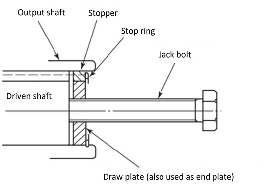
- (4) Remove the hollow output shaft from the driven shaft so that no excess force is applied between the case and the hollow output shaft. Prepare the removal plate (Table 1) and jack bolt (Table 2) and attach the jack bolt as shown in Figure 3 to ensure smooth removal.
Table 2 Jack bolt dimensions
| Size | Output shaft hole diameter | Jack bolt (Fully threaded) |
Size | Output shaft hole diameter | Jack bolt (Fully threaded) |
|---|---|---|---|---|---|
| SWJ50 | Φ30 | M12×80 | TD125H | Φ70 | M24×150 |
| SWJ63 | Φ35 | M12×80 | TD150H | Φ80 | M24×150 |
| SWJ70 | Φ40 | M12×80 | TD175H | Φ90 | M30×180 |
| EW/SW 80 | Φ50 | M16×100 | TD200H | Φ100 | M30×180 |
| EW/SW100 | Φ55 | M16×100 | TD225H | Φ110 | M30×180 |
| EW/SW125 | Φ70 | M24×150 | TD250H | Φ125 | M30×180 |
| EW/SW150 | Φ80 | M24×150 | TD280H | Φ130 | M36×250 |
| EW/SW175 | Φ90 | M30×180 | TD315H | Φ160 | M36×250 |
| EW/SW200 | Φ100 | M30×180 |
Figure 3: Jack bolt installation instructions
4-2-2. Flange installation and removal
1. Installation Procedure
When fixing the reducer to the driven machine (when no radial load acts on the reducer)
- (1) Insert the reducer onto the driven shaft.
- (2) When fixing, use the taps on the flange surface of the case.
- - For SWJ25 to 42, use the holes on the flange surface to secure with bolts.
- - For bolt size, mounting dimensions, pitch, etc., please refer to the table and diagram in item 2 of 4-1-2 above.
- (3) We recommend using the case's pilot joint for positioning. (SWJ25 does not have a pilot joint.)
Note: End plates are not required for flange mounting.
If the hollow output shaft is fixed with an end plate, thrust force will be applied to the hollow output shaft bearing, which may damage the bearing.
When fixing the reducer to the driven machine by flange mounting (when a radial load acts on the reducer)
- (1) Insert the reducer onto the driven shaft.
- (2) Adjust the radial runout of the driven shaft, leaving the axial direction free, and then install the reducer.
- (3) We recommend using the taps on the flange surface of the case to secure the reducer, and the spigot on the case for positioning. (SWJ25 does not have a spigot.)
- (4) After fixing the reducer, fix the axial direction of the driven shaft.
Note: If the axial direction of the driven shaft is fixed first, a thrust force will be applied to the hollow shaft bearing, which may damage the bearing.
2. Removal procedure
When the reducer is fixed to the driven machine (when no radial load acts on the reducer)
- (1) Loosen the flange bolts that secure the driven machine and reducer.
- (2) Remove the hollow output shaft from the driven shaft so that no excess force is applied between the case and the hollow output shaft. Prepare the removal plate (Table 1) and jack bolt (Table 2) and attach the jack bolt as shown in Figure 3 to ensure smooth removal.
When fixing the reducer to the driven machine by flange mounting (when a radial load acts on the reducer)
- (1) Keep the driven shaft in a balanced and stable state.
- (2) Loosen the flange bolts that secure the driven machine and reducer.
- (3) Remove the hollow output shaft from the driven shaft so that no excess force is applied between the case and the hollow output shaft. Prepare the removal plate (Table 1) and jack bolt (Table 2) and attach the jack bolt as shown in Figure 3 to ensure smooth removal.
4-2-3. Attaching and Removing Foot mount (EW-H Output Hollow Shaft Type)
When installing and removing, be sure to center the driven machine and reducer by referring to Section 4-1-1 for Foot mount, Section 4-2-1 for torque arm installation, and Section 4-2-2 for flange installation.
If the centering is incorrect, unexpected loads may occur, which may damage the bearings, shafts, etc.

