technical data Reducer Worm Reducer Selection
If you would like to see the selection procedures and important points, please proceed below.
If you would like to narrow down or tentatively select a product series,
Please click here.
If your usage conditions have been decided and you would like a detailed selection,
Please click here.
Selection Procedure
First, identify the selection table in the flowchart.
Next, for operating conditions that do not fall under Selection Tables 1 and 2 for the EWJ, EW, SWJ, and SW series (Selection Table 3), and for the TD series, please select using the following procedure.
The conditions required for selection include load torque or transmission kW, input rotation speed, reduction ratio, load characteristics, usage time, and start-stop frequency.
1. Determination of correction coefficient
All kW ratings table listed in Selection Table 3 are based on Service factor (Sf) of 1.0. Service factor the larger of these as the correction factor. For the nature of the load, refer to the load classification table by machine. If the machine name is not available, please select a similar machine or consult us.
Table 1: Service factor Table (Sf)
| Load Nature | Usage time (per day) | ||
|---|---|---|---|
| 2 | 10 | 24 | |
| U: Uniform load | 1.00 (1.25) |
1.00 (1.25) |
1.25 (1.50) |
| M: Load with some impact | 1.00 (1.25) |
1.25 (1.50) |
1.50 (1.75) |
| H: Load with large impact | 1.25 (1.50) |
1.50 (1.75) |
1.75 (2.00) |
Note
- 1) If the number of starts per hour is 10 or more, use the number in parentheses.
- 2) The above Service factor table is a general guideline. Please determine the usage coefficient taking into consideration the conditions of use.
Table 2. Thermal rating coefficient (EWJ, EW, SWJ, SW series)
| Input Rotation Speed r/min |
Size | Reduction ratio Operating time |
Thermal Rating Factor |
|---|---|---|---|
| 1750, 1450 | EWJ25 ~ 70 SWJ25 ~ 42 |
1/10 to 1/60 Continuous operation More than an hour |
1.3 |
| SWJ50 ~ 70 | 1.15 | ||
| 1750, 1450 | EW80 ~ 200 SW80 ~ 200 |
1/10 to 1/60 Continuous operation More than 2 hours |
1.5 |
| 1150, 950 | EW80 ~ 200 SW80 ~ 200 |
1.15 | |
| Other than the above | 1.0 | ||
2. Determine design kW and corrected torque
design kW or corrected torque is determined using formula 1.
design kW = Load kW × Correction coefficient (Equation 1)
Correction torque = load torque × correction coefficient...(Equation 1)
3. Deciding the reduction ratio
Decide the reduction ratio based on the input rotation speed to be used and the required output rotation speed. If the input rotation speed exceeds 1750 r/min, please contact us.
Note: The reduction ratio indicated in the model number of the TD series is the nominal reduction ratio. Please check the actual reduction ratio for single reduction or Double reduction.
4. Deciding on size and model number
Please select the size and model number that satisfies design kW or corrected torque from kW ratings table.
When using an input rotation speed of 100 r/min or less, select the output torque at 100 r/min in kW ratings table.
For the TD series, please check the following items for the selected size.
[Confirmation of equivalent heat capacity: TD series]
Determine the temperature correction coefficient (f1) from the ambient temperature you will be using and the temperature correction coefficient table (Table 3), calculate the equivalent heat capacity, and use Equation 2 to check whether it is within the capacity listed in the kW ratings table on each product page.
Equivalent heat capacity = Load kW (or torque) × f1......(Equation 2)
Table 3. Temperature correction coefficient table (f1) (TD series)
| Ambient temperature | Temperature Correction Coefficient |
|---|---|
| Below 30°C | 1.0 |
| Below 40°C | 1.3 |
| below 50°C | 1.5 |
5. Check the shaft load
Use formula 3 to check whether the radial load generated on the shaft is within the allowable radial load for each series.
Allowable radial load (N{kgf}) ≧ T × f × Lf R ...(Equation 3)
- T: Corrected torque (N・m {kgf・m})
- f: OHL coefficient (see table below)
- Lf: Position of action factor (see table below)
- R: Pitch circle radius of sprocket, pulley, etc. (m)
OHL coefficient (f)
| Chain | 1.00 |
|---|---|
| gear Toothed belt |
1.25 |
| V-belt Heavy-duty toothed belt |
1.5 |
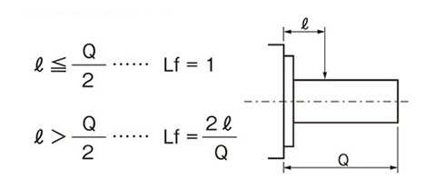
Solid output shaft type
Position of action factor (Lf)
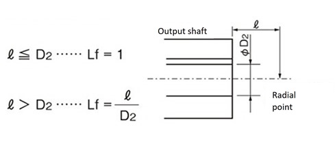
Hollow output shaft type
Position of action factor (Lf)
Checking the axial load
If an axial load is generated on the output shaft, check that it is within the allowable axial load for each series.
If radial and axial loads occur simultaneously, please contact us.
Alternating load
In applications where alternating loads are applied frequently, such as index drives, backlash in the reducer or play in the fastening parts may lead to unexpected problems.
If you are considering using this product for such purposes, please fill out the specifications confirmation sheet with your usage conditions and contact us.
6. Calculating the required input kW
Required input kW = Rated input kW × Load torque Rated output torque × Sf

