technical data Reducer Worm Reducer TERUS Selection
If you would like to see the selection procedures and important points, please proceed below.
If you would like to narrow down or tentatively select a product series,
Please click here.
If your usage conditions have been decided and you would like a detailed selection,
Please click here.
Selection Procedure
For the TERUS EWJGM, EWGM(R), SWJGM, SWGM(R), and TDGM(R) series, please select using the following procedure.
The conditions required for selection include motor capacity, load torque, input rotation speed, reduction ratio, load characteristics, usage time, and start-stop frequency.
1. Specification: Decide on A, B, C, or X type
Please choose the specifications that best suit your intended use.
- Type A: Standard specifications
......Highly versatile, highly efficient and output-oriented combination - B type: Self-locking
......A combination that emphasizes self-locking properties when stationary, suitable for lifting devices, inverting machines, etc. - C type: Eco specification
......Combination that prioritizes gear strength and takes into account impact loads from garbage disposals, crushers, etc. - X type: Special combination
......Gearmotor and worm sizes and speed ratios can be freely combined. (Please consult us separately.)
2. Determining Service factor
The output shaft allowable torque and motor kW in the characteristics table are all values when Service factor (sf) is set to 1.0. Select Service factor (sf) according to the load characteristics, operating time, and start-up frequency, and use the larger of the two as the correction factor.
For the nature of the load, please refer to the load classification table by machine. If the machine name is not listed, please select a similar machine or contact us.
Table 1: Service factor Table (Sf)
| Load Nature | Usage time (per day) | |||
|---|---|---|---|---|
| 0.5 | 2 | 10 | 24 | |
| U: Uniform load | 1.00 (1.00) | 1.00 (1.00) | 1.00 (1.25) | 1.25 (1.50) |
| M: Load with some impact | 1.00 (1.00) | 1.00 (1.25) | 1.25 (1.50) | 1.50 (1.75) |
| H: Load with large impact | 1.00 (1.25) | 1.25 (1.50) | 1.50 (1.75) | 1.75 (2.00) |
Note)
- (1) If the number of starts is 10 or more per hour, use the number in parentheses.
- (2) The above Service factor table is a general guideline. Please determine the coefficient based on the usage conditions.
3. Determining the correction torque
The required load torque or required motor kW is multiplied by the correction coefficient to determine the correction torque using formula 1.
Correction torque = Load torque × Correction coefficient (Equation 1)
design kW = Motor kW x Correction Coefficient (Equation 1)
4. Deciding the reduction ratio
The reduction ratio is determined from the input rotation speed to be used and the required output rotation speed.
Note: The reduction ratio indicated in the model number of the TERUS series is the nominal reduction ratio. Please check the actual reduction ratio.
5. Tentative determination of size and model number
Please provisionally select the size and model number that satisfies design kW or correction torque from the output shaft allowable torque in the characteristics table for each type.
6. Check the shaft load
Use formula 2 to check whether the radial load generated on the shaft is within the allowable radial load for each series.
Allowable radial load ≧ T × f × Lf R ......(Formula 2)
- T: Correction torque
- f: OHL coefficient
- Lf: Position of action factor
- R: Pitch circle radius of sprockets, pulleys, etc.
OHL coefficient (f)
| Chain | 1.00 |
|---|---|
| gear | 1.25 |
| Toothed belt | 1.25 |
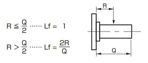
Solid output shaft type
Position of action factor (Lf)
Checking the axial load
If an axial load is generated on the output shaft, check that it is within the allowable axial load for each series.
Alternating load
If an alternating load is applied to a TDGM hollow output shaft (including Power-Lock), the strength of the mounting case taps, etc. must be checked.
Please check the applied load and contact us.
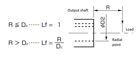
Hollow output shaft type
Position of action factor (Lf)
7. Deciding on size and model number
If the shaft load is not satisfactory, consider increasing the size and recheck the shaft load before selecting the final model number.

