technical data Reducer Servo Motor Reducer TERVO Handling
This page describes general information regarding the handling of the TERVO HMTK, GMTK, SWJMK, SWMK, EWJMK, and EWMK series.
For details, please refer to Instruction Manuals attached to the product.
Servo motor assembly procedure
When the motor shaft is a key shaft
- (1) Check that the key is correctly set on the motor shaft.
- (2) Apply the grease adhering to the inside of the input shaft to the motor shaft.
- (3) Align the key position of the motor shaft with the key groove of the input shaft and insert it.
This completes the motor installation.
When the motor shaft is round (input shaft clamp type)
- (1) Install the reducer so that the motor mounting surface is at the top.
- (2) Wipe off any rust, dust, rust-preventive oil, etc. from the motor shaft.
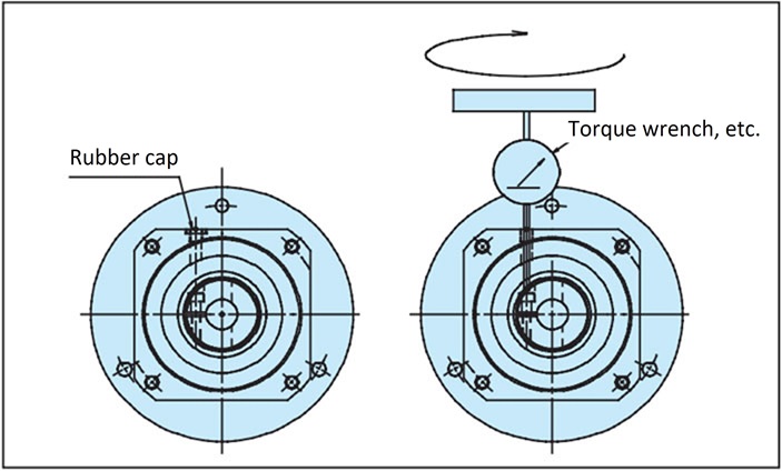
- (3) Remove the flange cap, turn the input shaft, and align the bolt head with the cap. Use an L-shaped wrench or similar tool to check that the set bolt is loose.
- (4) Insert the motor shaft gently and smoothly into the input shaft. Be careful not to insert the motor shaft at an angle.
- (5) After the spigot part is fully inserted, use the appropriate bolts and tighten them completely to the motor flange with the appropriate tightening torque for each bolt size.
- (6) Tighten the clamp set bolt of the input shaft using a torque wrench or similar tool to the tightening torque corresponding to the values in Tables 1, 2, and 3 below.
- (7) Attach the cap. This completes the motor installation.
Table 1. GMTK/HMTK clamp specification set bolt tightening torque
| GMTK | HMTK | Set bolt size |
Tightening torque |
|---|---|---|---|
| 0218U/L 0224U/L 0228U/L 0424U/L 0428U/L 0438U/L |
0220H 0222U 0230H 0228U 0430H 0428U 0435H 0438U |
M4 | 4.1N・m {0.41kgf・m} |
| 0728U/L 0738U/L 0742F/L 1538U/L 1542F/L |
0735H 0738U 0745H 0742U 1545H 1542U 1555H 1550U |
M5 | 8.5N・m {0.85kgf・m} |
| 2242F/L | 2245H 2242U 2255H 2250U | M6 | 14N・m {1.42kgf・m} |
Table 2. SWJMK/SWMK/EWJMK/EWMK Clamp set bolt size list
| Worm model number | Mount Code | E4 | G2/G5 | K2/K3/K4 | L1 | |
|---|---|---|---|---|---|---|
| Spout diameter | Φ50G7 | Φ70G7 | Φ110G7 | Φ114.3G7/H7 | ||
| Mounting pitch | PCD70 | PCD90 | PCD145 | PCD200 | ||
| EWJMK35, SWJMK35 | M3 | - | - | - | ||
| EWJMK42, SWJMK42 | M3 | - | - | - | ||
| EWJMK50, SWJMK50 | - | M4 | - | - | ||
| EWJMK63, SWJMK63 | - | M4 | M6 | M6 | ||
| EWJMK70, SWJMK70 | - | - | M6 | M6 | ||
| EWMK80, SWMK80 | - | - | M6 | M6 | ||
| EWMK100, SWMK100 | - | - | - | M6 | ||
Table 3. SWJMK/SWMK/EWJMK/EWMK Clamp set bolt tightening torque
| Clamp set bolt size | Tightening torque |
|---|---|
| M3 | 1.9N・m {0.19kgf・m} |
| M4 | 3.8N・m {0.39kgf・m} |
| M6 | 12N・m {1.22kgf・m} |
Tightening the clamp set bolt
Mounting a keyed motor to an input shaft clamp type
Motor shafts with keys can be used as clamp types in the same way as round shafts by removing the key.
Set the motor keyway 180 degrees opposite the clamp slit position.
Attach it to the reducer using the same procedure as for the round shaft.

