technical data Reducer Small Gear Motor Handling
This section describes general handling of Gear Motor, Hypoid Motor, and Croise Motor.
For details, please refer to Instruction Manuals attached to the product.
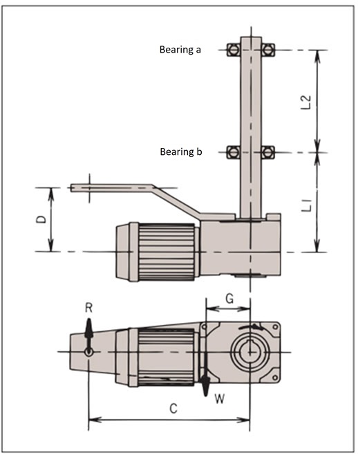
Torque arm design
When using a standard torque arm or designing and manufacturing your own torque arm, please check the strength of each element as follows:
1. Check the torque arm and fixing bolts
Check using torque arm reaction force R.
R = T + W × G C
2. Bearing selection
Check bearing reaction forces A and B.
A (bearing a) = L1 × (R - W) - D × R L2
B(bearing b) = (L1 + L2) × (R - W) - D × R L2
- T: Output torque N・m{kgf・m}
- W: Weight of reducer kg{kgf}
- R: Torque arm reaction force kg {kgf}
- G: Distance between the center of the driven shaft and the center of gravity of the reducer m
- C: Distance between the driven shaft center and the anti-rotation stopper m
- D: Distance between the center of the reducer and the anti-rotation stopper m
- L1: Distance m between the center of the reducer and bearing b
- L2: Distance between bearing a and bearing b m
*The output torque is + when rotating in the direction shown on the left, and - when rotating in the opposite direction.
Dimensions when using optional torque arm (approximate values)
| Model number | G |
|---|---|
| HMTA010-30H5~35H1200 HMTA020-30H5~200 HMTA020-45H600~1200 HMTA040-55H600~1200 |
0.10m |
| HMTA020-35H300~480 HMTA040-30H5~35H200 HMTR221-45H5~55H120 |
0.12m |
| HMTR075-35H5~55H480 HMTR151-55H100~200 |
0.13m |
| HMTA040-45H300~480 HMTR151-45H5~80 HMTR370-55H5~60FI |
0.15m |
| HMTR550-55H5~40FI | 0.26m |