technical data Reducer DCBL Hypoid Motor Selection
If you would like to see the selection procedures and important points, please proceed below.
If you would like to narrow down or tentatively select a product series,
Please click here.
If your usage conditions have been decided and you would like a detailed selection,
Please click here.
Selection
We can select the motor capacity based on the operating cycle, load torque, etc.
When making an inquiry, please use the selection request sheet.
1. Conditions
(1) Driving cycle
Output shaft rotation speed
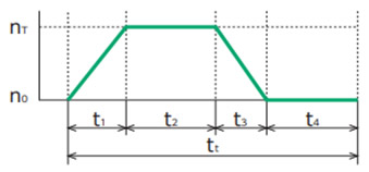
- n T: Maximum output shaft rotation speed (r/min)
- t 1: Acceleration time (sec)
- t2: Steady state time (sec)
- t 3: Deceleration time (sec)
- t 4: Stop time (sec)
- t t:Time for one cycle (sec.)
Output Torque
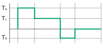
- T a: Acceleration torque (N・m)
- Tc: Steady-state torque (N・m)
- T b: Deceleration torque (N・m)
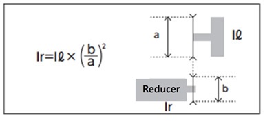
(2) Load moment of inertia Ir
Calculate the load moment of inertia Ir on the output shaft of the reducer from the table on how to calculate the moment of inertia
Ir: Load moment of inertia on the reducer output shaft (kg·m 2)
(3) Acceleration/deceleration torque T a, T b
Acceleration torque T a = △T a + T c
Deceleration Torque
△Ta = 2πIr × △na 60 × t1
Tb = △Tb - Tc
△Tb = 2πIr × △nb 60 × t3
- I r: Load moment of inertia on the reducer output shaft (kg·m 2)
{I r + (I g + I m) × i 2}
(Motor shaft converted reduction unit inertia + motor inertia) x speed ratio^2 (moment of inertia data) - △T a: Inertial acceleration torque (N・m)
- △n a: Rotational speed difference (r/min) △n a = n T- n o
- △T b: Inertial deceleration torque (N・m)
- △n b: Rotational speed difference (r/min) △n b = n T-no
(4) Steady-state torque T c
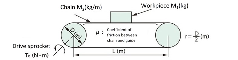 |
Tc = G(M1 + 2.1 × M2 × L) × μ × r G = gravitational acceleration: 9.80665m/s 2 |
 |
Tc = G(M1 + M2) × μ × ℓ 2 × π × η |
 |
Tc = GM × r |
2. Selection Procedure
| (1) Calculate the reduction ratio i |
i ≒
Nm
nT
Nm: Motor rotation speed |
||||||||
| ↓ | |||||||||
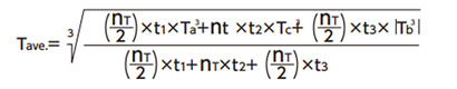
| (2) Calculate the average output torque |
|
||||||||
| ↓ | |||||||||
| (3) Deciding on size Average Torque Maximum torque |
f s: Series coefficient Maximum torque < Maximum torque of reducer output shaft |
||||||||
| ↓ | |||||||||
| (4) Calculate the average output shaft rotation speed n ave. |

|
||||||||
| ↓ | |||||||||
| (5) Check the rotation speed n ave. × i < reducer rated input rotation speed n T × i < Reducer maximum input rotation speed |
|
||||||||
| ↓ | |||||||||
| (6) Check the radial load on the output shaft | OHL < N: Allowable radial load of reducer* O.H.L = 2000 × Ta × f × Lf D D: Pitch circle diameter of sprocket, etc. (mm) |
||||||||
*Please refer to the allowable radial load in kW ratings table.
f: OHL coefficient
| Chain | Geared belt | V-belt |
|---|---|---|
| 1.0 | 1.25 | 1.5 |
Lf: Position of action factor
| ℓ/Q | 0.25 | 0.38 | 0.5 | 0.75 | 1 |
|---|---|---|---|---|---|
| Lf | 0.8 | 0.9 | 1 | 1.5 | 2 |
Reference length: Q
| Model number | speed ratio | Q |
|---|---|---|
| DCHM020 | 10 ~ 60 | 36 |
| DCHM040 | 10 ~ 50 | 42 |
| DCHM075 | 10 ~ 50 | 58 |
Series coefficient: fs
| Model number | Series Coefficients |
|---|---|
| DCHM | 1.7 |
Hollow output shaft
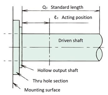
Q: Please refer to the table on the left for reference lengths.
Solid Output Shaft

Q: Please refer to the dimension table for each type for the reference length.
3. Check the output shaft overhang load
When attaching a sprocket, gear, belt, etc. to the central output shaft, or when attaching to a hollow shaft using case taps, make sure that the overhang load acting on the output shaft is below the allowable OHL of the small gear motor being used.
*When using a heavy-duty toothed belt, add installation tension to the calculation, regardless of the OHL coefficient (f) in Table 1.
[Overhang load calculation]
Allowable OHL ≧ 2000 × TF × f × Lf Dp
- TF: Correction torque
- f: OHL coefficient (Table 1)
- Lf: Position of action coefficient (Equation 1)
- Dp: Pitch diameter of sprocket etc. (mm)
Reference length: Q
| Model number | speed ratio | Q |
|---|---|---|
| DCHM020 | 10 ~ 60 | 36 |
| DCHM040 | 10 ~ 50 | 42 |
| DCHM075 | 10 ~ 50 | 58 |
Table 1. OHL coefficient: f
| Chain | Geared belt | V-belt |
|---|---|---|
| 1.0 | 1.25 | 1.5 |
Equation 1. Position of action factor: Lf
| ℓ/Q | 0.25 | 0.38 | 0.5 | 0.75 | 1 |
|---|---|---|---|---|---|
| Lf | 0.8 | 0.9 | 1 | 1.5 | 2 |
| Solid shaft | Hollow shaft |
|---|---|
|
Q: Please refer to the dimension table for each type for the reference length. |
Q: Please refer to the table on the left for reference lengths. |
4. Moment of inertia converted into motor shaft
| Model number | Reduction ratio | moment of inertia x10-4 kg m 2 |
|---|---|---|
| DCHM020-20H | 10 | 0.065 |
| 15 | 0.050 | |
| 20 | 0.045 | |
| 25 | 0.041 | |
| 30 | 0.040 | |
| 40 | 0.039 | |
| 50 | 0.038 | |
| 60 | 0.037 | |
| DCHM040-30H | 10 | 0.117 |
| 15 | 0.076 | |
| 20 | 0.060 | |
| 25 | 0.051 | |
| 30 | 0.047 | |
| 40 | 0.056 | |
| 50 | 0.052 | |
| DCHM075-35H | 10 | 0.306 |
| 15 | 0.209 | |
| 20 | 0.170 | |
| 25 | 0.146 | |
| 30 | 0.140 | |
| 40 | 0.158 | |
| 50 | 0.145 |
| Model number | Reduction ratio | moment of inertia x10-4 kg m 2 |
|---|---|---|
| DCHM020-22U | 10 | 0.068 |
| 15 | 0.051 | |
| 20 | 0.046 | |
| 25 | 0.041 | |
| 30 | 0.040 | |
| 40 | 0.039 | |
| 50 | 0.038 | |
| 60 | 0.037 | |
| DCHM040-28U | 10 | 0.133 |
| 15 | 0.083 | |
| 20 | 0.065 | |
| 25 | 0.054 | |
| 30 | 0.049 | |
| 40 | 0.059 | |
| 50 | 0.054 | |
| DCHM075-38U | 10 | 0.347 |
| 15 | 0.227 | |
| 20 | 0.180 | |
| 25 | 0.152 | |
| 30 | 0.145 | |
| 40 | 0.165 | |
| 50 | 0.149 |
DCBL Hypoid Motor
| Motor Capacity | brake | moment of inertia x10-4 kg m 2 |
|---|---|---|
| 0.2kW | No brakes | 1.154 |
| With brake | 1.159 | |
| 0.4kW | No brakes | 1.753 |
| With brake | 1.780 | |
| 0.75kW | No brakes | 12.761 |
| With brake | 12.918 |

