technical data Miter Bevel Gearbox Selection
If you would like to see the selection procedures and important points, please proceed below.
If you would like to narrow down or tentatively select a product series,
Please click here.
If your usage conditions have been decided and you would like a detailed selection,
Please click here.
ARA Gear Box selection
Conditions required for selection
(1) Load torque or transmission kW (2) Input rotation speed (3) Speed ratio (4) Load characteristics (5) Start/stop frequency
Selection Procedure
Considering the necessary conditions, the selection will be made according to the following procedure.
1. Determining Service factor
All kW ratings table in the catalog are values when Service factor is set to 1.0.
Determine Service factor Service factor Table 1 based on the conditions of use.
Table 1 Service factor
| Load Nature | Operating time | ||
|---|---|---|---|
| 2 hours | 10 hours | 24 hours | |
| Uniform Load | 1.00 (1.00) |
1.00 (1.25) |
1.25 (1.50) |
| Load with some impact | 1.00 (1.25) |
1.25 (1.50) |
1.50 (1.75) |
| Loads with large impacts | 1.25 (1.50) |
1.50 (1.75) |
1.75 (2.00) |
Note)
- 1. If the start/stop frequency is 10 or more times per hour or if the prime mover is a multi-cylinder engine, use the values in parentheses.
- 2. The above Service factor are general guidelines. Please determine the coefficients taking into consideration the conditions of use.
2. Determining the corrected torque or design kW
Considering Service factor (Table 1), calculate the corrected torque or design kW.
Corrected torque or design kW = (load torque or transmission kW applied to the ARA series) x Service factor (Table 1)
3. Deciding on the format
- - Select a size that satisfies the corrected torque or design kW at the rotational speed to be used from kW ratings table (see product page).
Also, check that the peak torque during start-up and shutdown is within 200% of the transmission capacity of the selected size. - - Determine the appropriate model number based on the shaft arrangement and rotation relationship above.
4. Check the radial load
When driving sprockets, gears, pulleys, etc. attached to the lateral shaft or cross shaft, check the radial load using the formula below.
・Radial load confirmation formula
Allowable radial load ≧
T × f × Lf
r
(Allowable radial load)
- T = Corrected torque N・m
- f = OHL coefficient (Table 2)
- Lf = Coefficient of operating position (Table 3)
- r = pitch circle radius of sprocket, pulley, etc. m
Note: If the formula on the left is not satisfied after checking the radial load, r, i.e., the pitch circle radius of the sprocket, pulley, etc., must be increased.
Table 2 OHL coefficient (f)
| Chain | 1.00 |
|---|---|
| gear Toothed belt |
1.25 |
| V-belts and heavy-duty toothed belts | 1.50 |
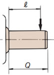
Table 3 Coefficient of action position (Lf)
| Load is at the center of the shaft or If it is further inward, ℓ ≦ Q 2 |
Lf = 1 |
|---|---|
| Load is from the center of the shaft If it is on the outside ℓ > Q 2 |
Lf = 2ℓ Q |
Q = Length of output shaft end ℓ = Position where radial load acts
Note) If a radial load and an axial load are applied at the same time, please contact us.
