Major Specifications ECHT-FLEX Coupling NES series
形番:NES250W-N**CXN**C
[Click to enlarge]
*The above is an image for illustrative purposes only. Please be sure to check the details below and in the drawings for accurate information.
PDF outline drawing
Important Notice: Regarding errors in PDF drawings
From August 4th to August 23rd, 2017
Spacer type and standard hub x standard hub
When combining, accidentally use a single type
The drawing was generated.
We sincerely apologize to customers who downloaded drawings for the relevant models during the above period, but we ask that you download them again.
DXF Drawing data
The minimum hole diameter for the applicable size,
The maximum hole diameter is displayed.
(Click here for a list of DXF data)
3D CAD data
標準価格
お問合せください
Delivery
お問合せください
| ※ | 3D CAD data will be provided via a link to CADENAS Web2CAD Co., Ltd.'s CAD Drawing Library site "PARTcommunity." |
| ※ | For inquiries regarding 3D CAD data and PARTcommunity, please contact Cadenas Web-to-CAD. For inquiries regarding Cadence Web-to-CAD Co., Ltd., please check here (external site). |
Catalogs and Instruction Manuals
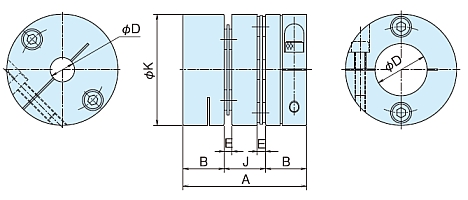
Transmission capacity and dimensions table
| Allowable Torque | Note 1) the best rotate speed r/min |
Note 4) Shaft hole diameter ΦD mm |
Dimensions in mm | Torsional rigidity | ||||||||||
|---|---|---|---|---|---|---|---|---|---|---|---|---|---|---|
| Shaft Hole Diameter range |
standard Shaft Hole Diameter |
A | B | E | ΦK | J | Through shaft maximum possible Shaft diameter |
Entire coupling | Disc only | |||||
| N・m | {kgf・m} | N・m/rad | {kgf・m/rad} | N・m/rad | {kgf・m/rad} | |||||||||
| 25 | 2.6 | 10000 | 10~25 | See table below | 59 | 20 | 3 | 55 | 19 | 22 | 11000 | 1100 | 22000 | 2200 |
| Axial direction Spring constant |
Note 3) Allowable misalignment |
Note 2) mass g |
Note 2) inertia Moment kg・m 2 |
Note 2) GD 2 {kgf・cm 2} |
|||
|---|---|---|---|---|---|---|---|
| N/mm | {kgf/mm} | Angular Misalignment deg |
Parallel Error mm |
Axial Displacement mm |
|||
| 11 | 1.1 | 2.0 | 0.28 | ±1.4 | 320 | 140×10-6 | 5.7 |
Note)
1. The maximum rotation speed is not a value that takes dynamic balance into consideration.
2. Mass, moment of inertia, and GD 2 are values for the maximum bore diameter.
3. The allowable misalignment is the value when the other two misalignments are zero.
4. The recommended tolerance for the mounting shaft is h7. However, the shaft diameter Φ35 is compatible with servo motor shafts with a tolerance of +0.010 to 0.
Standard bore diameters and transmission torque list for each bore diameter (N・m)
| bolt size | Tightening torque | Transmission torque N・m | |||||||||||||
|---|---|---|---|---|---|---|---|---|---|---|---|---|---|---|---|
| N・m | {kgf・m} | Standard bore diameter mm | |||||||||||||
| Φ10 | Φ11 | Φ12 | Φ14 | Φ15 | Φ16 | Φ17 | Φ18 | Φ19 | Φ20 | Φ22 | Φ24 | Φ25 | |||
| M4 | 3.8 | 0.39 | 25 | 25 | 25 | 25 | 25 | 25 | 25 | 25 | 25 | 25 | 25 | 25 | 25 |

