FLATVEYOR Major Specifications
- ■By incorporating a support member, it can be used with Long travel length than flat cables.
- ■Special cables and tubes are provided according to the conditions of use.
Structure

[Click to enlarge]
PDF outline drawing
Please contact us
DXF Drawing data
Please contact us
(Click here for a list of DXF data)
Catalogs and Instruction Manuals
Material
| Support Members | Engineering plastics | ||||
|---|---|---|---|---|---|
| Support member tube | PVC | ||||
| Stopper | PE | ||||
Basic specifications and capabilities

[Click to enlarge]
| Maximum travel length Note) 1 | Support member bending radius R40 ・・・ 1600mm | ||||||
|---|---|---|---|---|---|---|---|
| Support member bending radius R70 ・・・ 2200mm | |||||||
| Support member bending radius R100 ・・・ 2800mm | |||||||
| Support member bending radius R130 ・・・ 2800mm | |||||||
| Maximum travel speed m/min | 2m/sec | ||||||
| maximum acceleration | 4G | ||||||
| Operating temperature range | -10℃~80℃ | ||||||
| Maximum cable/tube outer diameter | 16mm or less | ||||||
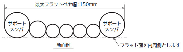
| Maximum width guideline | 150mm | ||||||
Note) 1. When the amount of supporting material is 0.4 kg/m.
2. bending radius of the support member may differ from bending radius when FLATVEYOR is installed.
Selection
All FLATVEYOR are products selected according to manufacturer specifications. Please fill out the inquiry sheet with your usage conditions and send it to us.
The specifications will be selected by us.
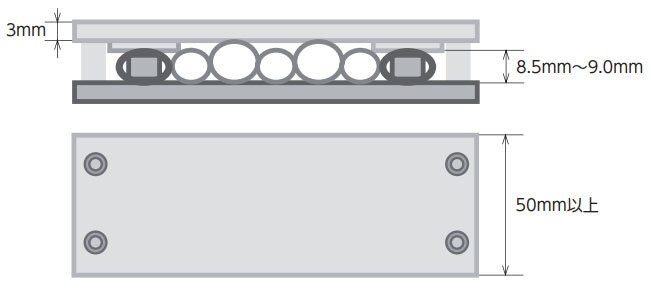
Handling of clamps for fixing FLATVEYOR
When the cable outer diameter is 8.5 mm or less
As shown in the diagram below, clamp length must be 50mm or more, clamp plate thickness must be 3mm or more,
The height inside the clamp should be 8.5mm to 9.0mm.
Please use a spacer or similar.
Also, tighten the four M6 bolts.

[Click to enlarge]
If the cable outer diameter is greater than 8.5 mm
As shown in the diagram below, clamp length must be 50mm or more, clamp plate thickness must be 3mm or more,
The inner height of the support member tube should be 8.5mm to 9.0mm.
Please use a spacer or similar.
Also, tighten the four M6 bolts.
[Click to enlarge]
Precautions
Please note that if the inner height of the support member tube is less than 8.5 mm, the support member may become deformed and break.
Option
Connector Installation
Please provide the connector manufacturer name, connector model number, terminal model number, and harness drawing. We will check whether we can handle your request and reply.
The parts used can be either procured by us or supplied by you.
Cable assembly not listed in the catalogue
It is also possible to incorporate cables that are not listed in our catalog. Please contact us.
Please note that, with the exception of defects during FLATVEYOR manufacturing, the supplied cables are not covered by our warranty.
Fixing Clamp
We can manufacture these. If you would like to manufacture your own, please refer to the recommended dimensions above.
Cable and air piping tubes
300V rated cable
| UL STYLE No. | 2464 |
|---|---|
| Rated temperature ℃ | 80 |
| Rated voltage V | 300 |
| Operating temperature range ℃ | -10~80 |
| conductor | Tin-plated annealed copper stranded wire |
|---|---|
| insulator | Special Elastomer |
| shield | Tin-plated annealed copper wire braid |
| sheath | Oil-resistant PVC (black) |
| Shield presence/absence | Minimum bending radius |
|---|---|
| No shielding | More than six times the cable outer diameter |
| With shield | At least 8 times the cable outer diameter |
| conductor | Core wire diameter mm | Logarithm | No shielding | With shield | Allowable current Note) A (30℃) |
||||||||||
|---|---|---|---|---|---|---|---|---|---|---|---|---|---|---|---|
| SQ mm2 |
AWG size |
composition | No. | Outer diameter mm |
Approximate mass kg/km |
Approximate mass kg/m |
Minimum bending radius Outer diameter x 6 times |
No. | Outer diameter mm |
Approximate mass kg/km |
Approximate mass kg/m |
Minimum bending radius Outer diameter x 8 times |
|||
| 0.1 | 28 | 49/0.05 | 0.74 | 1 | S1 | 3.3 | 13 | 0.013 | 20 | S32 | 3.8 | 21 | 0.021 | 31 | 2.4 |
| 2 | S2 | 4.4 | 20 | 0.020 | 27 | S33 | 4.8 | 30 | 0.030 | 39 | 1.8 | ||||
| 3 | S3 | 4.7 | 23 | 0.023 | 29 | S34 | 5.1 | 34 | 0.034 | 41 | 1.6 | ||||
| 4 | S4 | 5.0 | 27 | 0.027 | 30 | S35 | 5.4 | 38 | 0.038 | 44 | 1.4 | ||||
| 5 | S5 | 5.3 | 32 | 0.032 | 32 | S36 | 5.7 | 43 | 0.043 | 46 | 1.3 | ||||
| 6 | S6 | 5.6 | 36 | 0.036 | 34 | S37 | 6.0 | 48 | 0.048 | 48 | 1.2 | ||||
| 7 | S7 | 5.6 | 39 | 0.039 | 34 | S38 | 6.0 | 50 | 0.050 | 48 | 1.2 | ||||
| 8 | S8 | 6.0 | 43 | 0.043 | 36 | S39 | 6.4 | 56 | 0.056 | 52 | 1.1 | ||||
| 10 | S9 | 6.6 | 52 | 0.052 | 40 | S40 | 7.0 | 66 | 0.066 | 56 | 1.0 | ||||
| 0.2 | 25 | 102/0.05 | 0.93 | 1 | S10 | 3.7 | 17 | 0.017 | 23 | S41 | 4.2 | 25 | 0.025 | 34 | 3.8 |
| 2 | S11 | 5.0 | 27 | 0.027 | 30 | S42 | 5.4 | 37 | 0.037 | 44 | 3.0 | ||||
| 3 | S12 | 5.3 | 34 | 0.034 | 32 | S43 | 5.7 | 45 | 0.045 | 46 | 2.6 | ||||
| 4 | S13 | 5.7 | 39 | 0.039 | 35 | S44 | 6.3 | 51 | 0.051 | 51 | 2.3 | ||||
| 5 | S14 | 6.1 | 47 | 0.047 | 37 | S45 | 6.5 | 60 | 0.060 | 52 | 2.1 | ||||
| 6 | S15 | 6.6 | 54 | 0.054 | 40 | S46 | 7.1 | 69 | 0.069 | 57 | 2.0 | ||||
| 7 | S16 | 6.6 | 58 | 0.058 | 40 | S47 | 7.1 | 73 | 0.073 | 57 | 1.9 | ||||
| 8 | S17 | 7.1 | 65 | 0.065 | 43 | S48 | 7.6 | 80 | 0.080 | 61 | 1.8 | ||||
| 10 | S18 | 7.8 | 80 | 0.080 | 47 | S49 | 8.2 | 97 | 0.097 | 66 | 1.7 | ||||
| 0.3 | 23 | 108/0.06 | 1.09 | 1 | S19 | 4.0 | 20 | 0.020 | 24 | S50 | 4.4 | 28 | 0.028 | 36 | 5.2 |
| 2 | S20 | 5.5 | 36 | 0.036 | 33 | S51 | 5.9 | 44 | 0.044 | 48 | 4.0 | ||||
| 3 | S21 | 5.9 | 42 | 0.042 | 36 | S52 | 6.4 | 54 | 0.054 | 52 | 3.5 | ||||
| 4 | S22 | 6.3 | 51 | 0.051 | 38 | S53 | 6.7 | 64 | 0.064 | 54 | 3.2 | ||||
| 5 | S23 | 6.9 | 61 | 0.061 | 42 | S54 | 7.3 | 76 | 0.076 | 59 | 2.9 | ||||
| 6 | S24 | 7.4 | 72 | 0.072 | 45 | S55 | 7.8 | 87 | 0.087 | 63 | 2.7 | ||||
| 7 | S25 | 7.4 | 78 | 0.078 | 45 | S56 | 7.8 | 94 | 0.094 | 63 | 2.5 | ||||
| 8 | S26 | 8.0 | 88 | 0.088 | 48 | S57 | 8.4 | 105 | 0.105 | 68 | 2.4 | ||||
| 10 | S27 | 8.8 | 110 | 0.110 | 53 | S58 | 9.2 | 130 | 0.130 | 74 | 2.3 | ||||
| 0.5 | 21 | 177/0.06 | 1.36 | 1 | S28 | 4.6 | 26 | 0.026 | 28 | S59 | 5.0 | 37 | 0.037 | 30 | 7.7 |
| 2 | S29 | 6.4 | 51 | 0.051 | 39 | S60 | 6.8 | 67 | 0.067 | 41 | 5.8 | ||||
| 3 | S30 | 6.9 | 64 | 0.064 | 42 | S61 | 7.3 | 82 | 0.082 | 44 | 4.9 | ||||
| 4 | S31 | 7.5 | 75 | 0.075 | 45 | S62 | 7.9 | 94 | 0.094 | 48 | 4.7 | ||||
Note: The allowable current is a reference value, not a guaranteed value.
Cross section (example)
No shielding

With shield
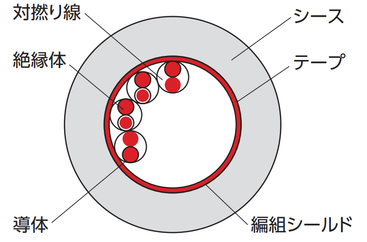
Insulator Identification
| Pair number | Insulation Color | |
|---|---|---|
| Type 1 core wire | Type 2 core wire | |
| 1 | blue | white |
| 2 | yellow | Purple |
| 3 | green | black |
| 4 | red | ash |
| 5 | Purple | orange |
| Pair number | Insulation Color | |
|---|---|---|
| Type 1 core wire | Type 2 core wire | |
| 6 | blue | tea |
| 7 | yellow | black |
| 8 | green | ash |
| 9 | red | orange |
| 10 | Purple | white |
600V rated cable
| UL STYLE No. | 2586 |
|---|---|
| Rated temperature ℃ | 105 |
| Rated voltage V | 600 |
| Operating temperature range ℃ | -10~105 |
| conductor | Tin-plated annealed copper stranded wire |
|---|---|
| insulator | Special Elastomer |
| shield | Tin-plated annealed copper wire braid |
| sheath | Oil-resistant PVC (black) |
| Shield presence/absence | Minimum bending radius |
|---|---|
| No shielding | More than six times the cable outer diameter |
| With shield | At least 8 times the cable outer diameter |
| conductor | Core wire diameter mm | core number | No shielding | With shield | Allowable current Note) A (30℃) |
||||||||||
|---|---|---|---|---|---|---|---|---|---|---|---|---|---|---|---|
| SQ mm2 |
AWG size |
composition | No. | Outer diameter mm |
Approximate mass kg/km |
Approximate mass kg/m |
Minimum bending radius Outer diameter x 6 times |
No. | Outer diameter mm |
Approximate mass kg/km |
Approximate mass kg/m |
Minimum bending radius Outer diameter x 8 times |
|||
| 0.5 | 21 | 100/0.08 | 1.52 | 2 | P1 | 5.3 | 34 | 0.034 | 32 | P35 | 5.7 | 45 | 0.045 | 46 | 9.2 |
| 3 | P2 | 5.5 | 41 | 0.041 | 33 | P36 | 5.9 | 53 | 0.053 | 48 | 8.0 | ||||
| 4 | P3 | 5.9 | 49 | 0.049 | 36 | P37 | 6.3 | 61 | 0.061 | 51 | 7.2 | ||||
| 5 | P4 | 6.3 | 58 | 0.058 | 38 | P38 | 6.7 | 72 | 0.072 | 54 | 6.7 | ||||
| 6 | P5 | 6.8 | 66 | 0.066 | 41 | P39 | 7.2 | 83 | 0.083 | 58 | 6.2 | ||||
| 8 | P6 | 8.0 | 90 | 0.090 | 48 | P40 | 8.4 | 110 | 0.110 | 68 | 5.6 | ||||
| 10 | P7 | 8.9 | 110 | 0.110 | 54 | - | 5.1 | ||||||||
| 0.75 | 19 | 150/0.08 | 1.73 | 2 | P8 | 5.7 | 41 | 0.041 | 35 | P41 | 6.1 | 53 | 0.053 | 49 | 12.0 |
| 3 | P9 | 5.9 | 51 | 0.051 | 36 | P42 | 6.3 | 62 | 0.062 | 51 | 10.5 | ||||
| 4 | P10 | 6.4 | 63 | 0.063 | 39 | P43 | 6.8 | 75 | 0.075 | 55 | 9.4 | ||||
| 6 | P11 | 7.4 | 87 | 0.087 | 45 | P44 | 7.8 | 105 | 0.105 | 63 | 8.1 | ||||
| 8 | P12 | 8.8 | 120 | 0.120 | 53 | P45 | 9.3 | 145 | 0.145 | 75 | 7.3 | ||||
| 10 | P13 | 9.7 | 145 | 0.145 | 59 | - | 6.7 | ||||||||
| 1.25 | 17 | 7/36/0.08 | 2.2 | 2 | P14 | 6.6 | 58 | 0.058 | 40 | P46 | 7.0 | 72 | 0.072 | 56 | 17.3 |
| 3 | P15 | 7.0 | 75 | 0.075 | 42 | P47 | 7.4 | 89 | 0.089 | 60 | 15.1 | ||||
| 4 | P16 | 7.5 | 92 | 0.092 | 45 | P48 | 7.9 | 110 | 0.110 | 64 | 13.5 | ||||
| 6 | P17 | 8.8 | 130 | 0.130 | 53 | P49 | 9.3 | 155 | 0.155 | 75 | 11.7 | ||||
| 2 | 15 | 7/57/0.08 | 2.6 | 2 | P20 | 7.4 | 79 | 0.079 | 45 | P51 | 7.8 | 94 | 0.094 | 63 | 23.6 |
| 3 | P21 | 7.8 | 105 | 0.105 | 47 | P52 | 8.2 | 120 | 0.120 | 66 | 20.6 | ||||
| 4 | P22 | 8.5 | 130 | 0.130 | 51 | P53 | 9.0 | 155 | 0.155 | 72 | 18.4 | ||||
| 6 | P23 | 10.0 | 185 | 0.185 | 60 | - | 15.9 | ||||||||
| 3.5 | 12 | 7/64/0.1 | 3.4 | 2 | P26 | 9.3 | 125 | 0.125 | 56 | P56 | 9.8 | 155 | 0.155 | 79 | 35.5 |
| 3 | P27 | 9.8 | 165 | 0.165 | 59 | - | 30.9 | ||||||||
Note: The allowable current is a reference value, not a guaranteed value.
Cross section (example)
No shielding

With shield
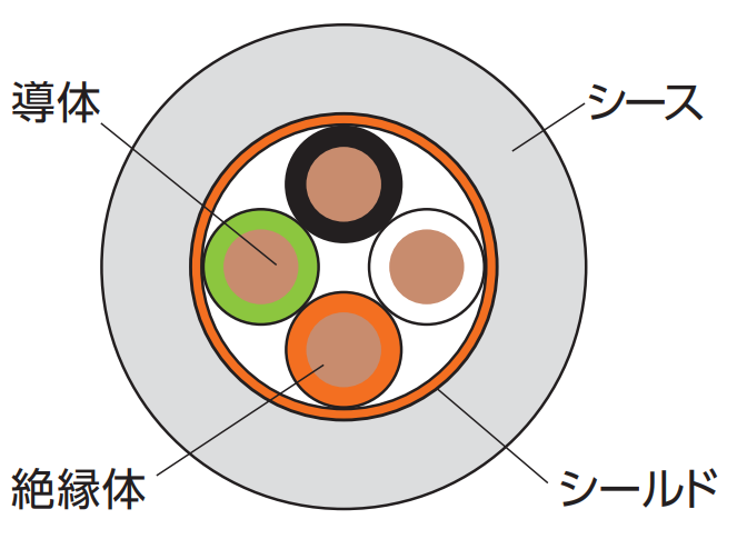
Insulator Identification
| Core number | Insulation Color |
|---|---|
| 1 | black |
| 2 | white |
| 3 | red |
| 4 | green |
| 5 | yellow |
| 6 | tea |
| 7 | blue |
| 8 | ash |
| 9 | orange |
| 10 | Purple |
Air piping tube
| No. | Specification | composition | |||||||||||||
|---|---|---|---|---|---|---|---|---|---|---|---|---|---|---|---|
| Outer diameter mm | Inner diameter mm | Maximum operating pressure MPa | Material | color | |||||||||||
| T1 | 4.0 | 2.5 | 0.8 (20℃) | Polyurethane | Black, yellow, blue, green, transparent, white | ||||||||||
| T2 | 6.0 | 4.0 | 0.8 (20℃) | Polyurethane | Black, yellow, blue, green, transparent, white | ||||||||||
| T3 | 8.0 | 5.0 | 0.8 (20℃) | Polyurethane | Black, yellow, blue, green, transparent, white | ||||||||||
| T4 | 10.0 | 6.5 | 0.8 (20℃) | Polyurethane | Black, yellow, blue, green, transparent, white | ||||||||||
Cable and tube precautions
Since FLATVEYOR welds adjacent supports together, please take the following precautions.
Material
The only cable jacket and tube materials that can be welded are PVC and polyurethane.
If you require a material other than those listed above, please contact us.
Outer diameter difference
The allowable difference in outer diameter between adjacent cables and tubes is approximately 30% of the smaller outer diameter. If the difference in outer diameter exceeds this limit, we may suggest using a dummy tube.
[Click to enlarge]
Installation procedure and method
Inquiry Sheet
お問合せ先について
ホームページからのお問合せ
英語でのお問い合わせは、つばきグループホームページの問合せページを開きます。
If you are purchasing this product outside of Japan, please contact your nearest overseas office at the link below.

