technical data Mechanical protector
Torque Limiter TL available
Torque setting
The slip torque of Torque Limiter is set by tightening or adjusting the adjustment nut or bolt.
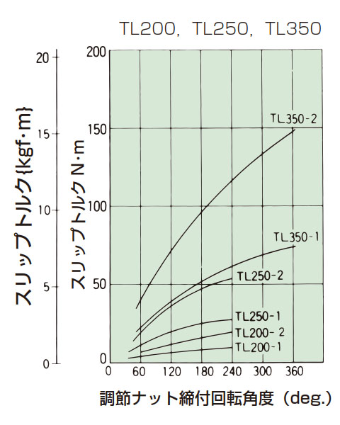
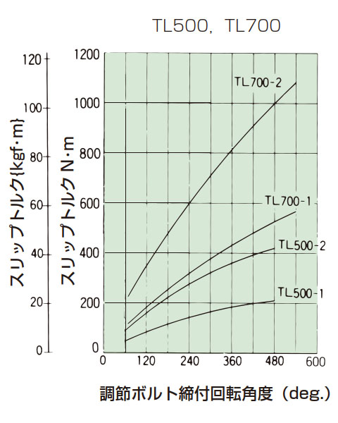
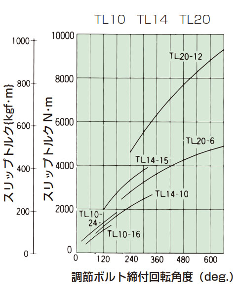
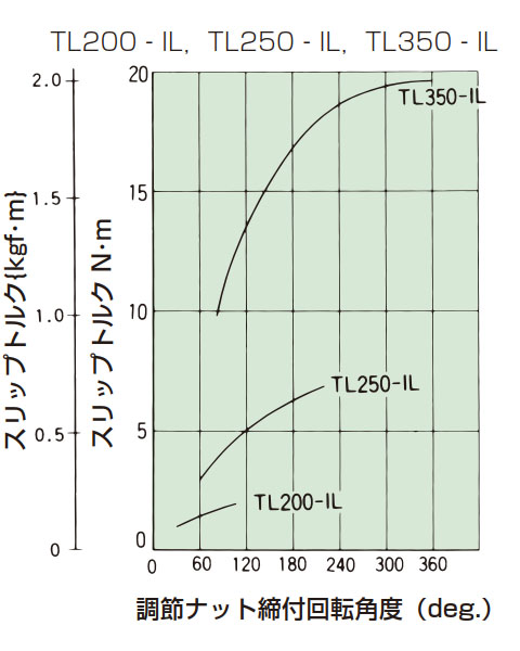
- (1) After installing Torque Limiter on the machine, perform several test runs, starting with a loosely tightened adjusting nut or adjusting bolt and gradually increasing the tightening amount to find the optimal tightening position. You can also use the tightening amount-torque correlation diagram (table below) to read the slip torque value for a given tightening amount of the adjusting nut or adjusting bolt. However, the torque for a given tightening amount will vary depending on the condition of the friction surface and other factors. The graph is only a guide; the most practical method is to perform a test run with a slightly looser tightening amount and find the tightening amount that is appropriate for the machine. If slip torque stability is particularly important, fully tighten the adjusting nut or bolt by hand, then further tighten it with a 60-degree wrench and allow it to slip approximately 500 revolutions to break in the friction surface. If the rotation speed is high, allow it to slip 500 revolutions in several steps.
- (2) We can also deliver the product with the center member already installed and set to the specified torque. In this case, the shaft hole must be pre-machined.
Tightening amount-torque correlation diagram
The 0 point is when the adjusting nut or adjusting bolt is tightened by hand to fix the disc spring.
[Click to enlarge]
[Click to enlarge]
[Click to enlarge]
[Click to enlarge]

[Click to enlarge]
Selection and production of center members
A sprocket gear can be clamped into Torque Limiter as a center member.
If you are selecting and manufacturing these center members yourself, please note the following points.
- (1) Please note that the minimum diameter of the center member is limited by Torque Limiter outer diameter (D).
For the minimum number of teeth when using sprockets for chain transmission, refer to the center member sprocket table below. - (2) The friction surfaces (both sides) of the center member should be finished to 3S to 6S.
- (3) The center member hole diameter should be finished to 3S to 6S according to the dimensional tolerance of the center member hole diameter in the dimension table.
- (4) The thickness of the part where the center member is clamped must be within dimension S in the dimension table.
Torque Limiter operation detection
Torque Limiter slips in the event of an overload to protect the machine, but if the drive source is not stopped, Torque Limiter will continue to slip.Continued slippage can cause abnormal wear or overheating of the friction plate, so the drive source must be stopped immediately.
As an example of how to detect slippage of Torque Limiter and stop the drive source, the following method using a proximity switch and digital tachometer is introduced.
Installation example
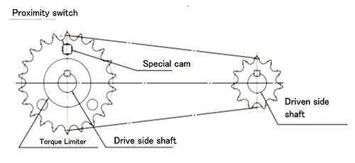
Format 1
When an overload is applied to the driven machine and the center member of Torque Limiter stops
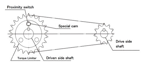
Format 2
When the driven machine is overloaded and Torque Limiter stops
Format 3
When using Torque Limiter as a coupling type and the center member stops when overloaded
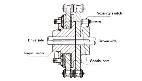
format 4
When using Torque Limiter as a coupling type and the main unit stops when overloaded
Avoid mounting method type 4 as much as possible because it is difficult to mount special cams. When using a Torque Limiter with a coupling type, use type 3.
By selecting the number of special cams as shown in the table below, slippage can be detected in approximately 1 to 10 seconds at the detection rotation speed.
Number of special cams and detection rotation speed
| Number of special cams | Detectable rotation speed range r/min |
|---|---|
| 1 | 6~60 |
| 2 | 3~30 |
| 3 | 2~20 |
| 4 | 1.5~15 |
| 5 | 1.2~12 |
| 6 | 1.0~10 |
| 7 | 0.85~8.5 |
| 8 | 0.75~7.5 |
| 9 | 0.67~6.7 |
| 10 | 0.6~6.0 |
Reference connection diagram
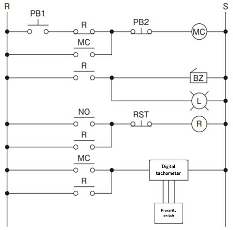
- PB1: Motor operation push button
- PB2: Motor stop push button
- RST: BZ, L Reset push button
- MC: Electromagnetic contactor for motor
- R: Auxiliary relay
- NO: Digital tachometer output a contact
- BZ: Buzzer
- L: Lamp
Digital tachometer: Omron H7CX-R11-N
Proximity switch: Omron Corporation TL-N5ME2
Note: We recommend the above Omron digital tachometers and proximity switches.
For details, please refer to the catalog published by Omron Corporation.
Special cam dimensions and installation
The special cam is screwed onto the driven side.
Use a screw lock or similar to prevent loosening.
Special cam reference diagram
*Please prepare this yourself.
Center member sprocket
When using a sprocket as a center member, please note the following:
The table below shows the case where a sprocket is used as the center member and chain power is transmitted.
- (1) When using mounting types 1 and 2, the minimum number of teeth that the chain will not hit the special cam (as shown in the reference diagram)
- (2) The minimum number of teeth that prevents the chain from hitting the friction plate when using Torque Limiter alone
- (3) Bush length
- (4) Sprocket hole diameter (center member hole diameter)
| Model number | sprocket Hole Diameter (Center Member hole diameter) |
Minimum number of teeth on sprockets used | ||||||||||||||||||
|---|---|---|---|---|---|---|---|---|---|---|---|---|---|---|---|---|---|---|---|---|
| RS35 | RS40 | RS50 | RS60 | RS80 | RS100 | RS120 | RS140 | RS160 | ||||||||||||
| minimum Number of teeth |
Bush length |
minimum Number of teeth |
Bush length |
minimum Number of teeth |
Bush length |
minimum Number of teeth |
Bush length |
minimum Number of teeth |
Bush length |
minimum Number of teeth |
Bush length |
minimum Number of teeth |
Bush length |
minimum Number of teeth |
Bush length |
minimum Number of teeth |
Bush length |
|||
| TL200 | 30+0.03 0 |
△20 | 3.8 | 16 | 6 | - | - | - | - | - | - | - | - | - | - | - | - | - | - | |
| TL250 | 41+0.05 0 |
- | - | 20 | 6.5 | 17 | 6.5 | - | - | - | - | - | - | - | - | - | - | - | - | |
| TL350 | 49+0.05 0 |
- | - | 26 | 6.5 | 21 | 6.5 | 18 | 9.5 | 15 | 9.5 | - | - | - | - | - | - | - | - | |
| TL500 | 74+0.05 0 |
- | - | - | - | △29 (30) |
6.5 | 25 | 9.5 | 19 | 9.5 | - | - | - | - | - | - | - | - | |
| TL700 | 105+0.05 0 |
- | - | - | - | - | - | △33 (35) |
9.5 | 26 | 12.5 | 21 | 12.5 | 18 | 12.5 | - | - | - | - | |
| TL10 | 135+0.07 0 |
- | - | - | - | - | - | - | - | - | - | △29 (30) |
12.5 | 24 | 15.5 | △22 | 19.5 | - | - | |
| TL14 | 183+0.07 0 |
- | - | - | - | - | - | - | - | - | - | △39 (40) |
15.5 | △33 (35) |
15.5 | △29 | 19.5 | △26 | 23.5 | |
| TL20 | 226+0.07 0 |
- | - | - | - | - | - | - | - | - | - | △54 | 15.5 | △46 (60) |
15.5 | △40 | 19.5 | △35 | 23.5 | |
- Notes: 1. △ marks are not standard A-type sprockets. If using a standard stock sprocket, please use the number of teeth in parentheses.
- Note) 2. The bushing length is for reference only.
| Model number | sprocket Hole Diameter (Center Member hole diameter) |
Minimum number of teeth on sprockets used | ||||||||||||||||||
|---|---|---|---|---|---|---|---|---|---|---|---|---|---|---|---|---|---|---|---|---|
| RS35 | RS40 | RS50 | RS60 | RS80 | RS100 | RS120 | RS140 | RS160 | ||||||||||||
| minimum Number of teeth |
Bush length |
minimum Number of teeth |
Bush length |
minimum Number of teeth |
Bush length |
minimum Number of teeth |
Bush length |
minimum Number of teeth |
Bush length |
minimum Number of teeth |
Bush length |
minimum Number of teeth |
Bush length |
minimum Number of teeth |
Bush length |
minimum Number of teeth |
Bush length |
|||
| TL200 | 30+0.03 0 |
△25 | 3.8 | 19 | 6 | - | - | - | - | - | - | - | - | - | - | - | - | - | - | |
| TL250 | 41+0.05 0 |
- | - | 24 | 6.5 | 20 | 6.5 | - | - | - | - | - | - | - | - | - | - | - | - | |
| TL350 | 49+0.05 0 |
- | - | 30 | 6.5 | 24 | 6.5 | 21 | 9.5 | 17 | 9.5 | - | - | - | - | - | - | - | - | |
| TL500 | 74+0.05 0 |
- | - | - | - | 32 | 6.5 | △28 (30) |
9.5 | 21 | 9.5 | - | - | - | - | - | - | - | - | |
| TL700 | 105+0.05 0 |
- | - | - | - | - | - | 36 | 9.5 | △28 (30) |
9.5 | △23 (24) |
12.5 | 20 | 12.5 | - | - | - | - | |
| TL10 | 135+0.07 0 |
- | - | - | - | - | - | - | - | - | - | △31 (32) |
12.5 | 26 | 15.5 | △23 | 19.5 | - | - | |
| TL14 | 183+0.07 0 |
- | - | - | - | - | - | - | - | - | - | △41 (45) |
15.5 | 35 | 15.5 | △30 | 19.5 | △27 | 23.5 | |
| TL20 | 226+0.07 0 |
- | - | - | - | - | - | - | - | - | - | △56 (60) |
15.5 | △47 (60) |
15.5 | △41 | 19.5 | △36 | 23.5 | |
- Notes: 1. △ marks are not standard A-type sprockets. If using a standard stock sprocket, please use the number of teeth in parentheses.
- Note) 2. The bushing length is for reference only.

