technical data Mechanical protector selection
If you would like to see the selection procedures and important points, please proceed below.
If you would like to narrow down or tentatively select a product series,
Please click here.
Torque Keeper TFK selection
When using Torque Keeper in personnel transport or lifting equipment, please take measures on the equipment side to prevent accidents involving personnel or falls.
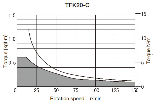
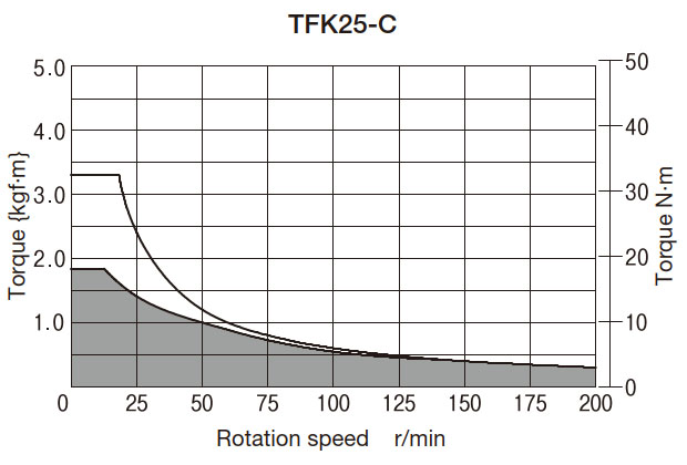
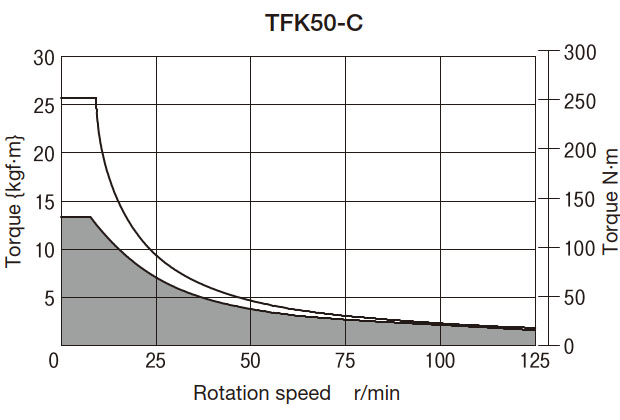
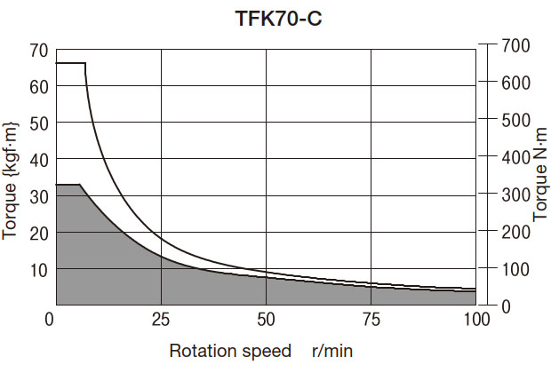
- 1. Determine the usage conditions from the table below according to the intended use, and then determine the size from the TN curve diagram at the end of the page.
Purpose of use Usage conditions Determining size Accumulation Determine the following items for each conveyor's Torque Keeper. - (1) Slip torque
- (2) Slip rotation speed
- (3) Slip time (conveyor stop time)
- (4) Connection time (conveyor operation time)
- (5) Daily usage time
Determine the size so that the slip torque and slip rotation speed are within the allowable values on the TN curve diagram (below the curve).
If the slip time is longer than the connection time or if the usage time exceeds 8 hours per day, We recommend using it within 10 minutes.
Braking Determine the following items for Torque Keeper of each machine device. - (1) Brake torque
- (2) Rotational speed
- (3) Slip time (duration of braking)
- (4) Engagement time (time when the brake is not applied)
- (5) Daily usage time
However, in the case of continuous slip, (3) and (4) are not required.
Determine the size so that the brake torque and rotation speed are within the allowable values of the TN curve (below the curve).
If the slip time is longer than the connection time or if the usage time exceeds 8 hours per day, We recommend using it within 10 minutes.
dragging Determine the following items for Torque Keeper of each machine device. - (1) Slip torque
- (2) Slip rotation speed
- (3) Slip time
- (4) Connection time
- (5) Daily usage time
Determine the size so that the slip torque and slip rotation speed are within the allowable values on the TN curve diagram (below the curve).
If the slip time is longer than the connection time or if the usage time exceeds 8 hours per day, We recommend using it within 10 minutes.
- 2. Check that the shaft hole range of Torque Keeper you have decided satisfies the shaft diameter to be installed.
- 3. Slip torque setting
For each model number of Torque Keeper, the torque is set to 50% of the maximum value of the set torque range (see product page), and the torque curve is attached when shipped.
This 50% torque is called the 0 point, and slip torque is set based on this 0 point.
For details, please refer to Section 2 of Instructions (see here).
Points to note when selecting
- 1. Please note that if water, oil, or other substances get into the friction surface, the torque will decrease and stable slip torque will not be obtained.
- 2. The TN curve applies to ambient temperatures up to 40°C. If the temperature exceeds this range, please contact us.
- 3. If the slip torque for the shaft diameter you are using is smaller than the set torque range of Torque Keeper, please contact us.
- 4. Backlash will occur if the rotation direction is reversed. This product cannot be used in devices where backlash is unacceptable.
The TN curve { } is a reference value.
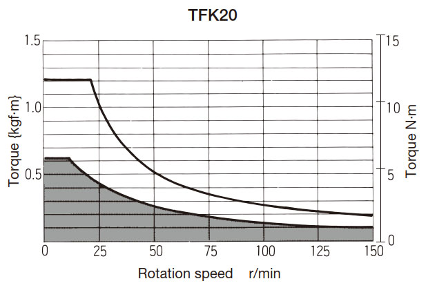
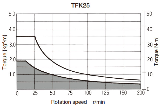
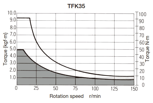

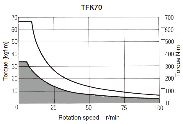
Note) The TN curve is based on the allowable temperature of Torque Keeper.
If you need a more stable slip torque We recommend using it within the following conditions.
However, please note that if the rotation speed is below 30 r/min, stick-slip may occur and the torque may not be stable.
The stick-slip phenomenon is a phenomenon in which friction surfaces repeatedly stop and slide.